Digital technologies/3D printing/3D printing- Beginner
This video shows a short overview of the 3D printing process with an Ultimaker 2+ from downloading Cura to starting the print:
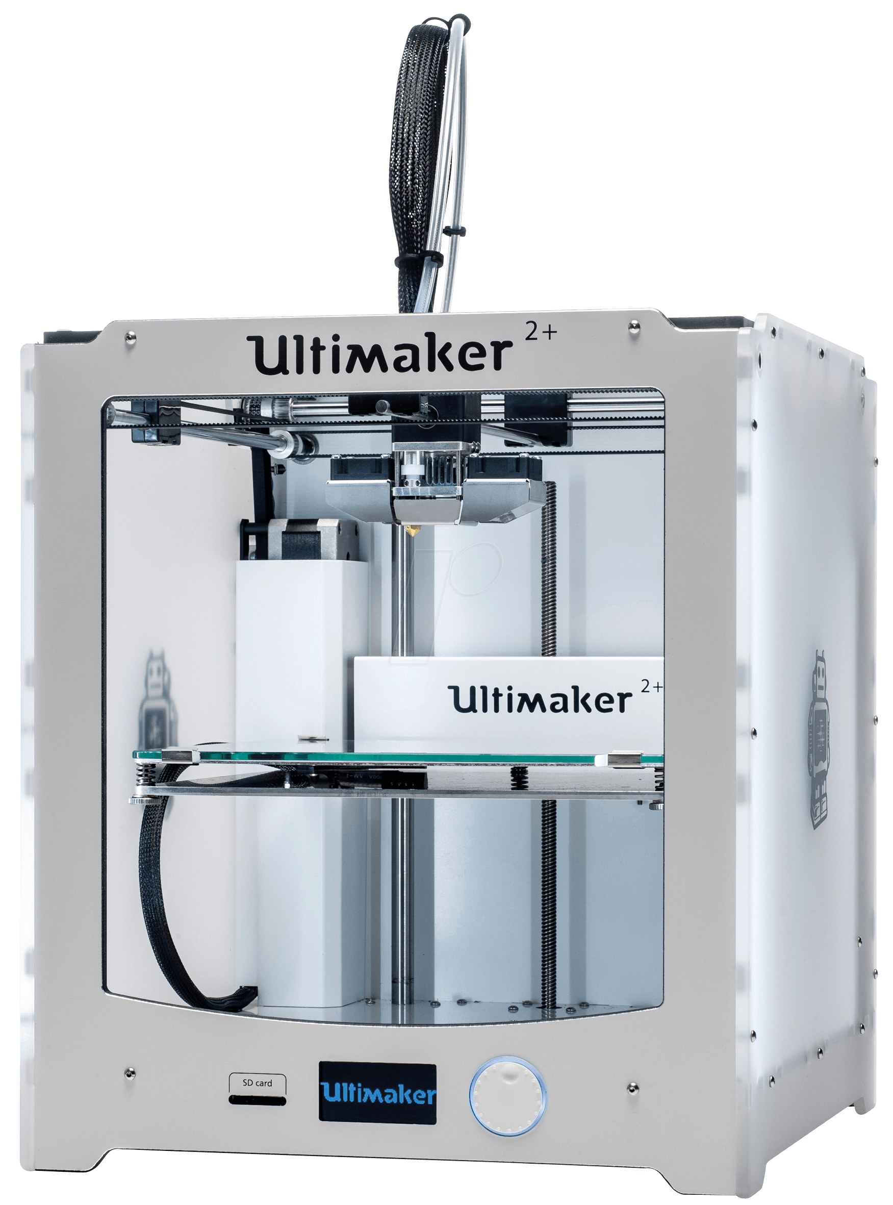
3D printing is an additive manufacturing process which creates a three-dimensional object from a digital model. At the uOttawa Makerspace, we use FDM (fused deposition modeling) which works by slicing the model into layers and then printing one layer on top of the other. The type of printer, and the options that are fitted to the printer, determine the capabilities in terms of accuracy, speed, and complexity a printer is capable of. The printer extruder and nozzle combination will dictate what materials the printer is capable of using. Multiple extrusion heads enable for different materials to be used during the same print and are common on more commercially-targeted products but can also be fitted to high-end personal-use models. This can enable a printer to use weaker (or even dissolvable) support material for easy removal, or the ability to add colour schemes to a print for aesthetic purposes. Heated build plates are fairly common, and are used to improve the quality of prints by reducing the heat stress placed on a component during printing and cooling. In addition, many printers are open source projects, enabling users to edit the printer’s software, and even use it to build their own printer. The material most commonly used in the Makerspace is a type of plastic known as PLA (Polylactic acid). This plastic is used for 3D printing because of its relatively low melting point and very low shrinkage rate. While the Makerspace owns a variety of FDM printer models, this beginner page will focus on the Ultimaker 2+ which is the main model of printer used.
Most of the material in this wiki page is also covered in the CEED's interactive trainings.
If you wish to follow the virtual 3D printing training, it is available at this link.
How do FDM Printers Work?
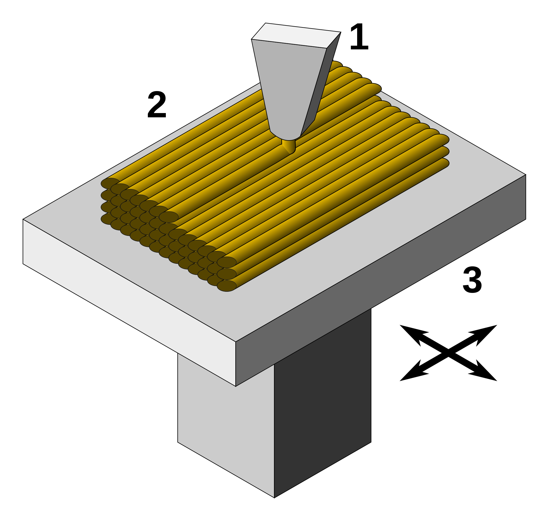
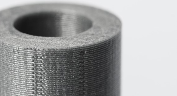
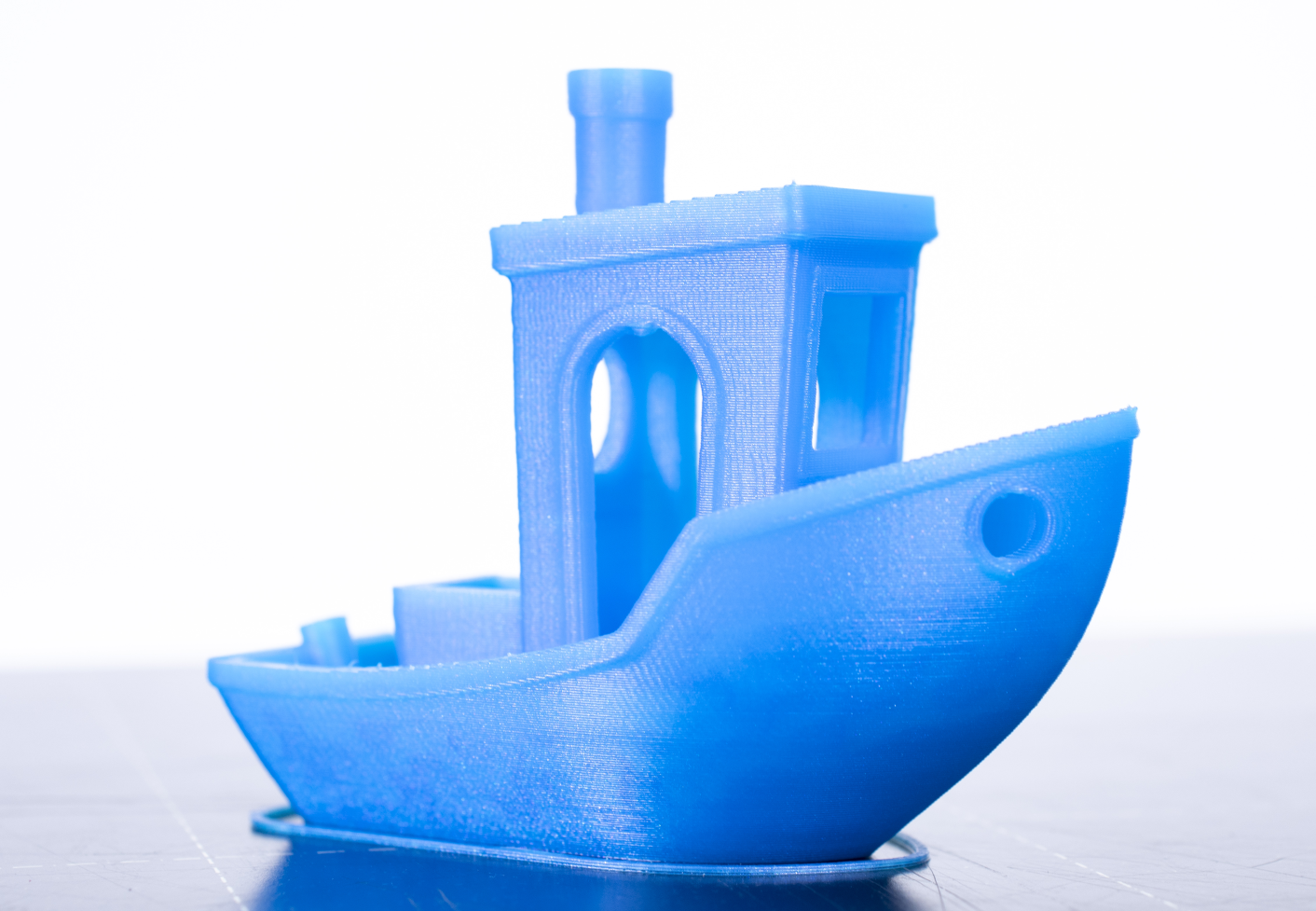
Fused deposition modelling (FDM) printers extrude melted material through a nozzle. As this happens, the nozzle is moved along a predetermined toolpath (a set of spatial coordinates), laying the extruded material on existing surfaces along the way. The toolpath is generated from CAD models in a software called a slicer software, named this way given that it slices 3D models in thin 2D layers which when stacked reform the original model.
Important Parameters
It is important to keep a few parameters in mind when FDM printing. Using the proper parameters will ensure that your print comes out right!
Nozzle Size
The nozzle size is an important parameter that affects the quality of the print you will obtain. Depending on the size of your print, as well as the desired quality, you may choose different nozzle sizes. Larger nozzles will be able to output more material such that prints on large nozzle printers will take less time (provided that other parameters such as layer height and printer speed are adjusted to take the larger nozzle into account). On the opposite side of the spectrum, smaller nozzle sizes will lead to a slower print, but finer feature qualities. At the Makerspace, we have 0.25mm, 0.4mm, 0.6mm and 0.8mm nozzles on our printers, the most popular sizes being 0.4mm and 0.8mm. Most desktop printers will have a 0.4mm nozzle size by default as this size strikes a nice balance between quality of print and print times. Laws of geometry being what they are, however, the amount of material you can output through the nozzle of your printer increases by a power of 2 as you increase nozzle sizes, such that you can expect to reduce printing times by roughly a factor of 4 by going from a 0.4mm nozzle to a 0.8mm nozzle (don't rely solely on presets to try to replicate these results, other settings need tweaking such as layer height and printer speed to reproduce this ratio of nozzle size to print time).
Layer Height
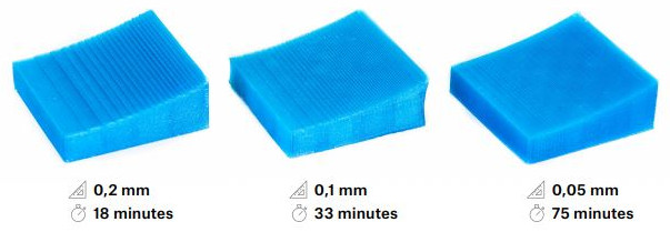
The Layer height is the second and most obvious parameter to tweak in order to obtain the preferred results. Larger layer heights will lead to coarser resolution in height (along the Z axis). Lower layer heights will lead to higher resolutions along Z, but will also increase the print time drastically. Note that using larger nozzles will allow you to use larger layer heights due to the extra volumetric flow obtainable. See below for an example.
Print Speed
The print speed is another one of those obvious parameters that will affect print times. Since the beginner slicing methods do not include modifications to print speed, going over this parameter was considered out of the scope of beginner knowledge and such print speed will be discussed in the intermediate page.
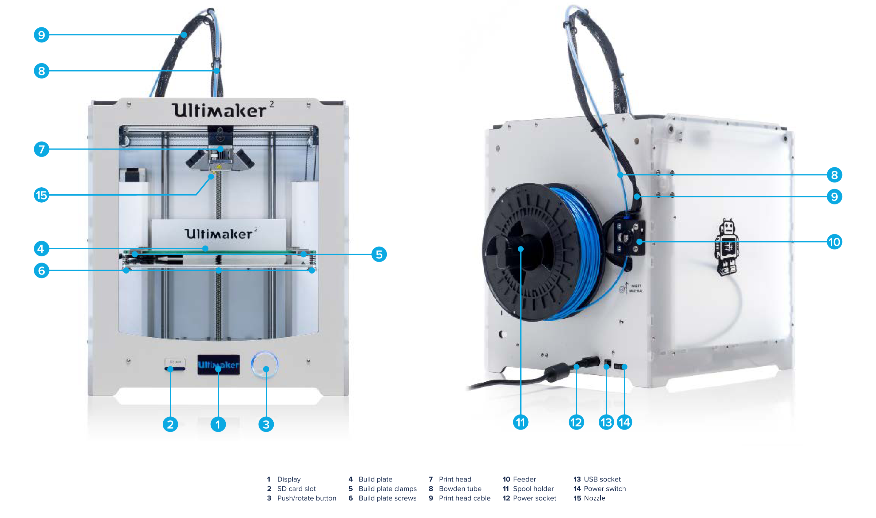
FDM Printer Components
Extruder and Nozzle (CAUTION: HOT!)
The extruder heats and pulls partially melted filament into the nozzle. During a print, the extruder and nozzle will heat up to over 210°C, so exercise caution around it. The location of the printer nozzle and extruder is controlled on an axis system (typically) made up of belts and gears. This assembly can be moved while the printer is idle by gently pulling on the extruder/nozzle assembly, being careful as parts of this assembly can be extremely hot even after a print has finished. If the printer is printing, or has recently been printing, the motors will still be engaged. Set the printer to idle and wait a few minutes, or power off the machine to disengage the motor lock.
Build Plate (CAUTION: HOT!)
The build surface is where the printed part is placed on. On most of the Makerspace printers the build plate is heated to 60°C (and can go as high as 110°C) during printing, so exercise caution around it. The plate can be raised or lowered while the printer is idle by going to Maintenance→Advanced→Raise/Lower Build Plate.
Filament Spool
The filament spool can be found attached to the back of the printer. The spool is essentially a filament roll. As the printer uses up the filament, the spool unrolls. Before printing, it is a good habit to check filament levels on the printer. You may find steps for replacing the filament in the intermediate page.
Which 3D printers do we have?
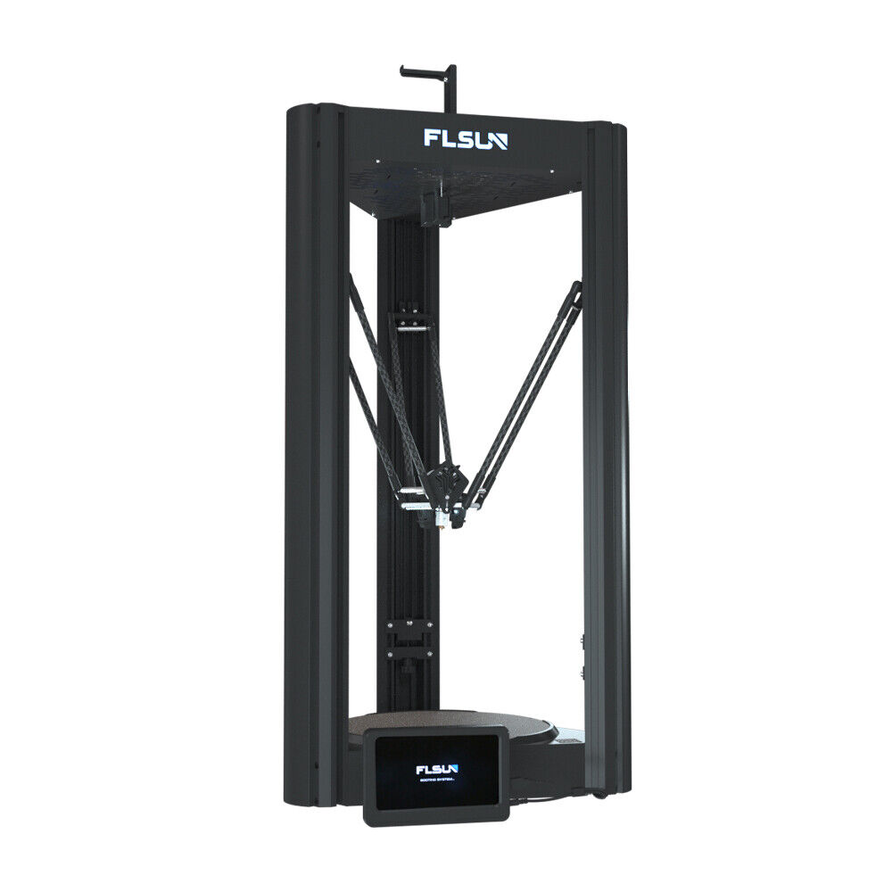
The following are the printers available for use at the Makerspaceː
| Slicer | Cura |
|---|---|
| Build Volume | 223 × 223 × 205 mm |
| Compatible materials | PLA, ABS, Flexible, etc |
| Minimum Layer Height | 0.06 mm |
| Heated Build Plate | Yes |
| Slicer | Cura |
|---|---|
| Build Volume | 215 × 215 × 200 mm |
| Compatible materials | PLA, PVA, Flexible, etc |
| Minimum Layer Height | 0.02 mm |
| Heated Build Plate | Yes |
| Slicer | MakerBot Print |
|---|---|
| Build Volume | 285 × 153 × 155 mm |
| Compatible materials | PLA |
| Minimum Layer Height | 0.1 mm |
| Heated Build Plate | No |
| Slicer | DigiLab 3D |
|---|---|
| Build Volume | 230 × 150 × 140 mm |
| Compatible materials | PLA |
| Minimum Layer Height | 0.1 mm |
| Heated Build Plate | No |
| Slicer | ideaMaker |
|---|---|
| Build Volume | 305 × 305 × 605 mm |
| Compatible materials | PLA, ABS, PVA, Flexible |
| Minimum Layer Height | 0.01 mm |
| Heated Build Plate | Yes |
| Slicer | Cura |
|---|---|
| Build Volume | 300 × 300 × 410 mm |
| Compatible materials | PLA, ABS, Flexible, etc |
| Minimum Layer Height | 0.05 mm |
| Heated Build Plate | Yes |
| Slicer | Eiger |
|---|---|
| Build Volume | 320 × 132 × 154 mm |
| Compatible materials | Nylon, Onyx, Carbon Fiber, Fiberglass, Kevlar |
| Minimum Layer Height | 0.1 mm |
| Heated Build Plate | No |
| Slicer | GrabCAD Print |
|---|---|
| Build Volume | 254 × 254 × 305 mm |
| Compatible materials | ABS, Soluble support |
| Minimum Layer Height | 0.254 mm |
| Heated Build Plate | Yes |
| Slicer | GrabCAD Print |
|---|---|
| Build Volume | 254 × 254 × 254 mm |
| Compatible materials | PLA, ABS, ASA, TPU, Soluble support |
| Minimum Layer Height | 0.127 mm |
| Heated Build Plate | Yes |
| Slicer | ChituBox |
|---|---|
| Build Volume | 218.88 × 123.12 × 250 mm |
| Compatible materials | Standard, ABS-like, rubber, etc |
| Minimum Layer Height | 0.01 mm |
| Heated Build Plate | No |
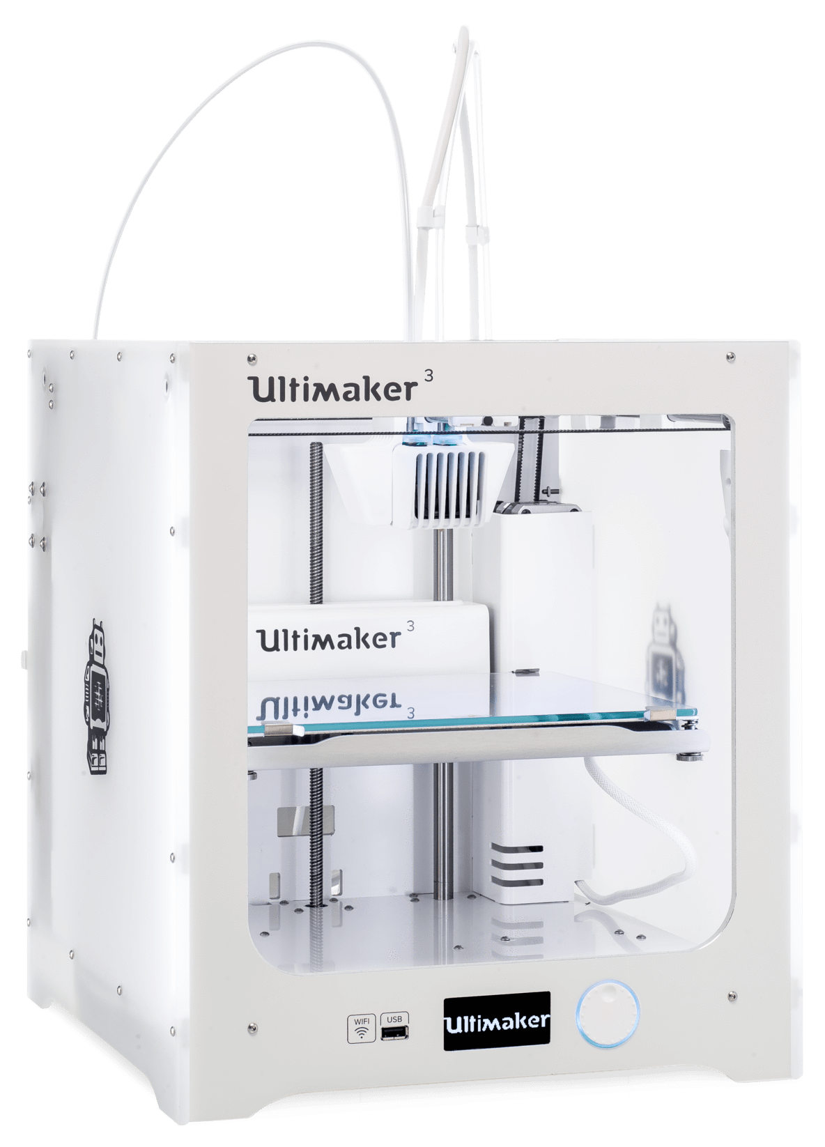
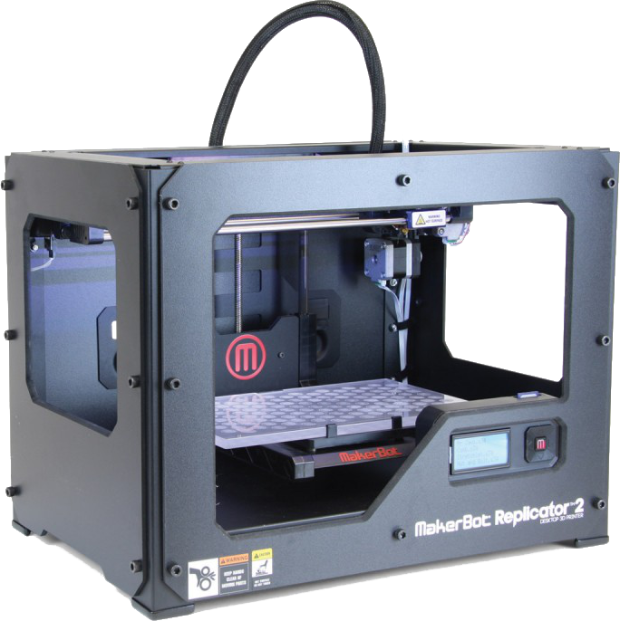
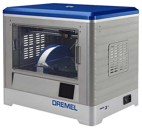
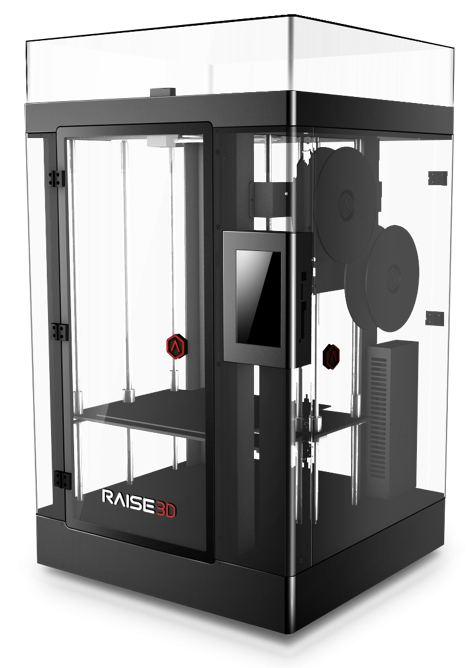
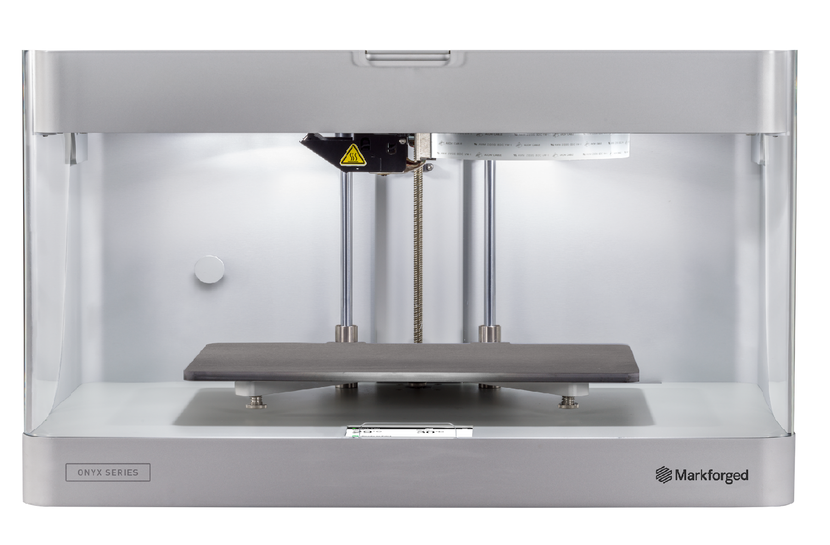
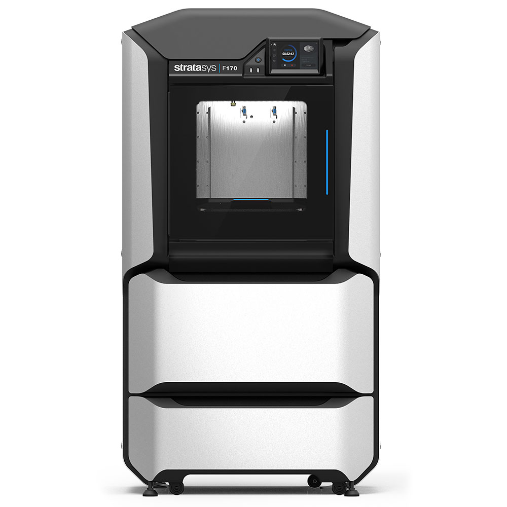
Most of the time, prototyping projects at the Makerspace will make use of the Ultimaker 2+. However, if a product requirement or design refinement calls for the use of other materials, better quality, faster print times, etc., some printers can be much more suitable. For instance, the Ultimaker 3 can print with various materials and is equipped with two extruder heads. However, this printer is extremely slowǃ For faster prints, the Dremel and Makerbot Replicator 2 printers are faster than the UM3 and even the UM2%2B, which can be increasingly important in a production or a rapid prototyping environment. The other printers listed, the Makerspace charges for as they are specialty printers. These (Raise and the Mark II) are extremely reliable printers. They can also perform overnight prints which greatly expands the realm of possibilities in print size, reliability and quality due to the slower speeds which can be afforded. The Mark II is especially suited for load bearing prints as it uses carbon fiber reinforced nylon and can lay continuous carbon/glass/kevlar fibers inside the prints for added rigidity. Feel free to consult the pages for each printer for more information on each printers' recommended slicer settings, use cases, and design resources.
Safety Considerations for FDM 3D Printing
Burn Hazard
Since FDM 3D printers melt materials, these carry an important burn hazard. Refrain from touching the 3D printer nozzle (200°C and hotter) and build plate (60°C and hotter). Hot parts are typically labelled on machines, but it can happen for the labelling to become worn down, and such it is important for you to know of these hazards so you may protect yourself against them.
Respiratory Hazard
It has been reported that materials melted by FDM printers can release harmful airborne particulates. It is important to use 3D printers in well ventilated areas or to use printers equipped with an air extractor. Air quality measurements of our Makerspace (STEM 107) have been professionally taken with 24 Ultimaker 2+ printers running for extended periods of time (as would be the case on a very busy day at the Makerspace). Thanks to proper ventilation of the space, the particulate concentration measured is well below regulatory limits.
Fire Hazard
Since the 3D printing process involves lots of heat and plastics, most of which are flammable, if the plastic being used runs out or accumulates around the printer nozzle and the temperature sensors limiting the nozzle temperature malfunctions, the printer could catch fire from overheating. This is why unsupervised (such as overnight) printing is prohibited on printers that have no shutoff mechanisms that would avoid conditions that may lead to the printer catching fire.
Pinch Hazard
Since printers have exposed moving parts, and the movements of the print head can be unexpected, the printers present a pinch hazard. Avoid introducing body parts close to a printer's moving parts.
Bodily Harm Hazard
While bodily harm hazards are not applicable to the small FDM printers in our Makerspace, they may be very real on larger printers where the drive mechanisms are very powerful to account for fast and accurate movements of a heavy print head. As a general rule when working with industrial machinery, please refrain from introducing any parts of your body within the range of movement of the print head or near exposed moving parts of machinery while it is powered on.
3D printing in our Makerspace
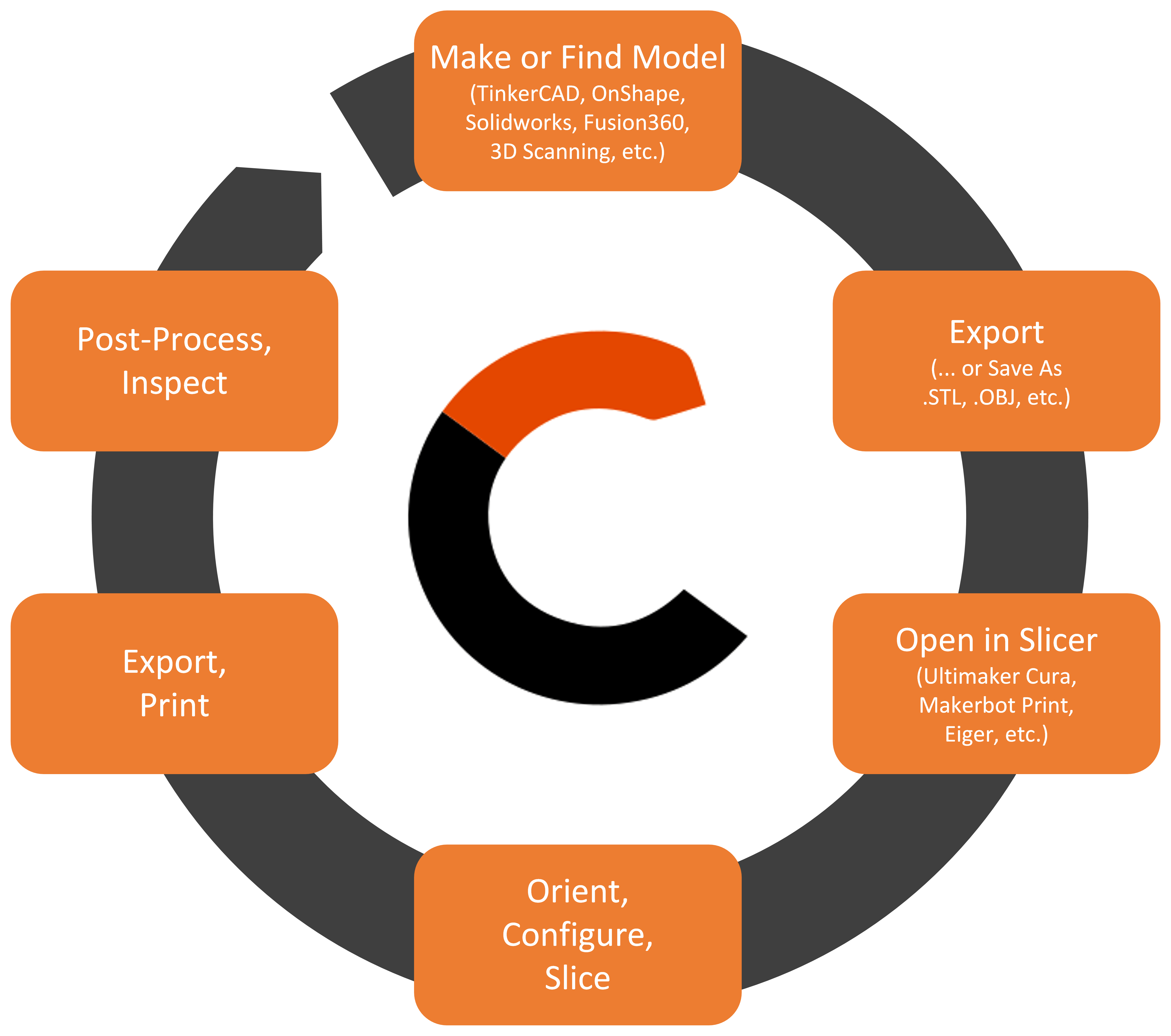
At the uOttawa Makerspace we have several different types (brands) of printers. When 3D printing in our Makerspace, you will encounter either the Ultimakers, MakerBots, or Dremels. In general, at a high level, the process for 3D printing is always the same. Typically, 3D printing on a hobbyist level is an iterative process in which you may have to tweak your models for the printer you are using. The following flowchart is a generalized yet important view of the typical workflow for 3D printing in the Makerspace.
Create or Find a 3D model
There are many ways to create or find a 3D model. If you want to browse through a library, Thingiverse or Youmagine. These sites are a great way to inspire yourself. If you are more of a do it yourself type of person there are several programs you can try.
If you are a beginner, try Tinkercad. This is a browser based 3D design application that is very simple to learn. For more information check out this handy guide. If you need something a little more advanced, you can use Solidworks, AutoCAD, Fusion360 or any other 3D modeling software. If you have your own components you would like to reverse engineer, you may also 3D scan them in the Makerspace!
Save or download the model as an stl
What is an stl file? It is a stereolithography (an old cad software) file format, but is was later adapted as a standard file format. STL stands for "standard triangle language". This type of file uses a web of polygons to describe a 3D object. It is this easiest and the default file type with most of 3D printing software.
In Tinkercad, click on Export a new window will pop up and then select *.STL
In Solidworks, click File→Save As. A new window will appear. Choose the file type *.stl.
Slicing
Open Model
Your stl file contains a set of triangular faces in 3D space. If you send this to a 3D printer, it will not know what to do. A slicer “slices” the 3D object into layers and then generates machine code (contained in a gCode file). Different printers work better with different slicers. The slicers need to be downloaded onto your computer. If you happen to not have access to a personal computer in our space, note that all our computers have all the software required to slice a print for any of the printers available for you to use.
Slice the Model for your printer
All Ultimaker printers have Cura as a slicer
- Open the file in Cura.
- Select the settings you want for your print (have a look at the next section to see how to do this, including reorienting and moving your part).
- Click slice (have a look at the preview of your slice if you want to see the toolpath slice by slice).
- Make sure the print will finish within Makerspace Open Hours: If a print is not finish before closing time, it will be cancelled by the employee and you will have to restart the next time Makerspace is open.
- Save to file (this creates a gCode file). Note: you may skip this step if you do not care for keeping the file on your computer.
- Save the gCode file to an SD card.
Start the print
Starting your print is very simple. Simply save your file to an SD card and click print.
- Save your file to an SD card. Any size SD card will work (gCode files are very small).
- Walk over to the printer and insert the card into the SD card slot located on the front of the printer.
- Turn on the printer. There is an on/off switch located at the back, on the left hand side of the Ultimaker. This is also a good time to make sure that there is sufficient filament loaded into the printer.
- Using the knob, select print. To “select” you simply press on the knob. This will take you to the SD card page, scroll through the files and select yours. Usually the most recent files are found at the bottom of the list. Selecting the file should start your print.
- We ask that you remain with your print for the first few layers. If you print fails and you are not there to tend to it, we will
- Be slightly annoyed as failed prints can damage the printers;
- Remove your print and free up the printer for someone else.
Use Cases for Prints in our Makerspace
The 3D printers in our Makerspace are for hobbyist and very low volume production projects. It is to be understood that these are the printers owned by the space since those are the people for which the space exist: students and hobbyists who are getting their first exposures to additive manufacturing but also those people who would like to use the space for personal projects. For this reason, it is free for you to print with PLA or ABS (ABS being on request since all printers are loaded with PLA by default). The Ultimaker 2+, our main model of printer is easy to maintain, user friendly, and CURA (its recommended slicer) is packed with features that allow for tuning the printer for you to be able to experiment and eventually obtain the result you want. This comes with advantages and disadvantages. This can be advantageous if you want to run with a variety of different qualities or settings (i.e.: great for learning about 3D printing!). On the disadvantageous side, this means the prints do not always work at the simple click of a button, and even if they do, they might not be a good representation of the part that you wanted to make (due to manufacturing defects such as warping, lack of overhangs, improper overhang placement, under- or over-extrusion, etc.).
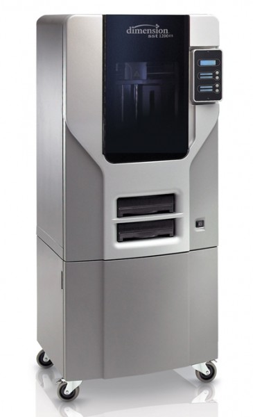
Industry-grade printers are the opposite. You will find that you have very little control over the parameters of the print, and the printer will be slow at printing, but the print will come out almost perfect most times. The Makerspace has the Makrforged Mark II as well as a Dimension 1200es printer for those who would like to get professional, industry-grade prints, but since the consumables for those printers are expensive and since not many people use these printers, the makerspace charges for prints made on them. If you think your application requires specialty materials or the extra quality that these industry grade printers provide, please do not hesitate to submit a print order through our system. We'll be happy to work with you on getting your part manufactured.
With the large amount of modifications you can make to your print settings as well as the fact parts printed in the Makerspace are typically PLA, parts printed in the Makerspace are perfect for small prototype enclosures, prototype organic shapes such as ergonomic designs, flexible (clamping) shaft stops, spacers or linear bearing housings (to name a few). They can also be used for prototype bracketing for low load applications. They are not for the manufacturing of extreme precision components or components that will encounter high loads.
Choosing your Slicer Settings as a Beginner
Since the Ultimakers are the most frequently used printers at the Makerspace, this article will be focused on the use of the "Cura" slicer, specifically Cura version 4.x.x. While this article may be specific to Cura, the software is based on an open source engine, so the same principles and settings should carry over to any slicer. This article will also focus only on the beginner "Recommended" settings interface.
Choose your 3D Printer
After installing Cura, you will be prompted to select your model of 3D printer. If you are printing at the Makerspace, this means you must select the Ultimaker 2+ or the Ultimaker 3 from the "Add a non-networked printer" window. Once selected, your Cura window should now display a visual representation of the interior available print volume.
Load your 3D Model
Once the correct 3D printer has been selected, load your model (.stl or .obj file) into Cura. This can be done by either dragging the file and dropping it into the Cura window, by clicking File -> Open Files (Ctrl+O), or by clicking the "Folder shaped" icon.
Position your Part on the Print Bed
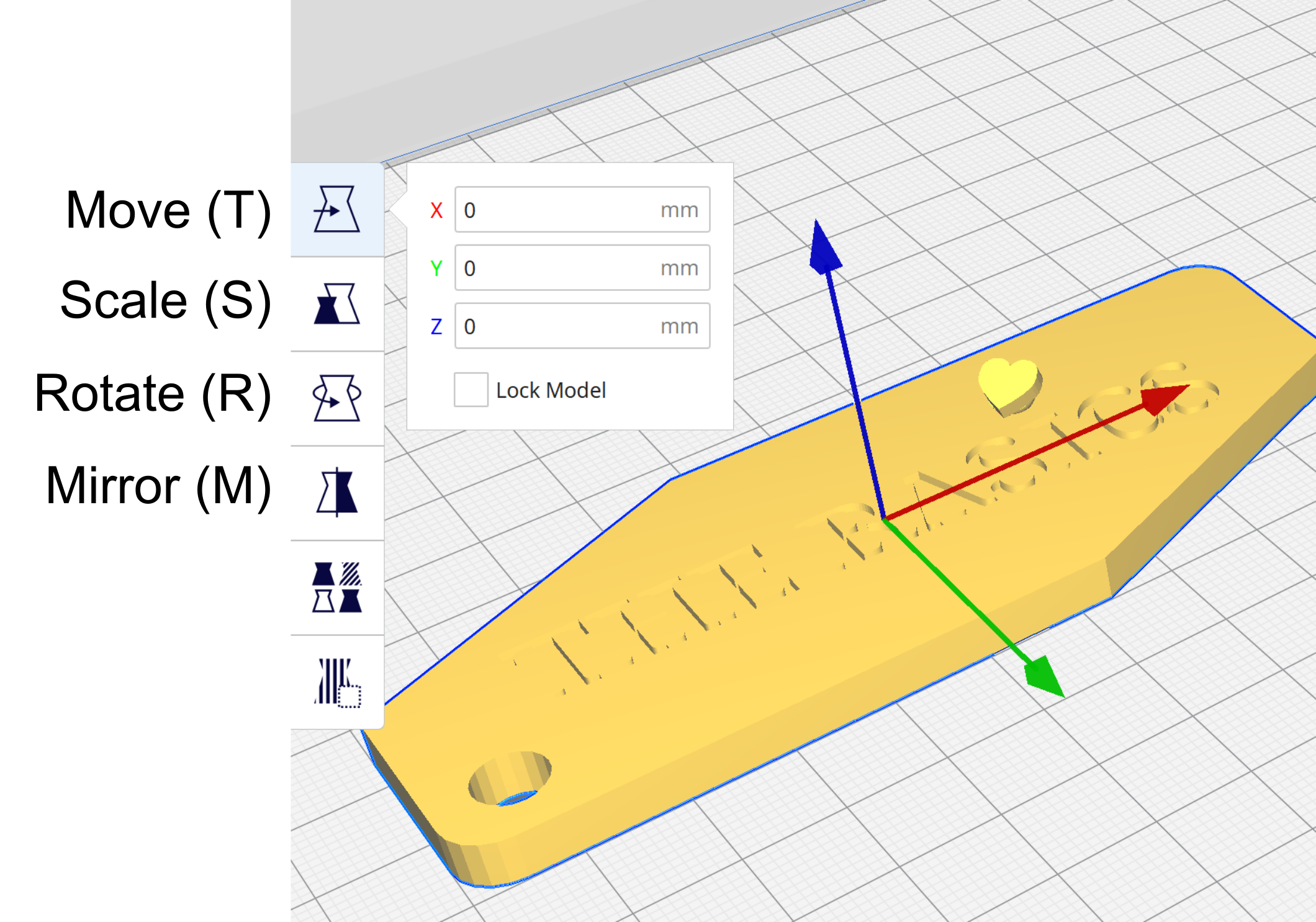
In Ultimaker Cura, moving your part around, rotating it, scaling it, or mirroring it, are very simple tasks. All you have to do is select your component, and from the choices on the left side of your screen, you may perform any of these aforementioned operations. Have a look at the tools that are at your disposition in the picture on the right.
Choose your Layer Height
Under the "Print settings" window, you will notice a slider referred to as "Profiles - Default", with numbers ranging from 0.06 to 0.6. The numbers refer to the layer height (sometimes referred to as "resolution") in millimeters, which is the vertical (Z-axis) height of each layer of plastic the printer lays down. The lower the layer height, the longer it will take to print, but the vertical quality (slopes) will be better. If your model lacks any slopes or curves running vertically, lower layer height numbers will only take longer to print, without adding any major improvements in quality.
Weigh the pros and cons for your specific model, decide on what layer height you want to use, and click on the slider which layer height you want to print in. In most cases, 0.15mm layer heights is a good balance of speed and quality.
Choose your Infill Percentage
To save on material, rather than completely fill a print a solid part with plastic, 3D printers will print what is called an "infill". Infills are usually by default a grid-like pattern that gives a 3D printed part rigidity and density. The "Infill (%)" slider allows you to select how dense (in percentage) the grid pattern inside the model will be, 0% being completely hollow, and 100% being completely solid. The higher the infill percentage, the stronger your part will be, but the longer it'll take to print.
It is a common misconception that 100% is always the best solution to creating a strong part. While 100% infill will create the strongest possible part, the ratio between printing time and part strength worsens as you increase the infill density, especially after approximately 60%. Selecting 100% is therefore often a waste of time and material in comparison to lower infills.[5]
In other words, if your part will not be facing any mechanical strain, we recommend you select an infill percentage between 5-20%. If high strains are expected and thus strength is required, use 60% at the very most.
Supports
Support towers are columns of printed material (usually the same material as your printed model), designed to add support to any "un-printable areas" during the printing process. The support towers are designed to be "easy to remove" once the print has finished (you may find that this isn't always the case however), and for many models it may be necessary to enable supports in order to ensure successful printing. Once your print is completed, you will have to remove the support material with your hands, or with tweezers if necessary.
Ideally, you would have designed your model to have as little overhangs or suspended parts as possible, though sometimes that will be unavoidable. By clicking the "Support" check box on Cura will have the software automatically generate support towers to any areas of your print that the software determines as a "challenging area" (overhangs, parts suspended mid-air etc...). If you are unsure whether your model needs supports, keep the box checked to be safe.
Adhesion
You'll notice that this box is checked by default. In the context of the "Recommended Settings" window on Cura, "Adhesion" refers to an outer thin "brim" of plastic printed around the model (there are different types of adhesion, which will be explained in-depth in the advanced article). This brim is to ensure that the part stays in place during the printing process. The brim of plastic should peel off very easily, so it is extremely beneficial and there are almost no downsides to having this setting enabled. As a beginner, we recommend that you keep this box checked.
Previewing a Slice
Previewing a slice can be a valuable tool in that it can save you lots time. Once a model is sliced, most software have a preview function that will simulate the final print. Cura allows simulating a print by going to the "Preview" tab. Previews will have extra features showing, such as support geometry and the brim, to name some. The preview will also allow you to see your print, slice by slice, using the slider on the right of the screen. This allows you to see the part infill geometry. The slice-by-slice preview will also let you see if all your desired features will come out well with the slice settings you chose.
It should be noted that Cura can open G-Code files, but only for previewing purposes. The .STL or .OBJ that was used to create a G-Code file cannot be restored from G-Code using slicer software.
When to Use Supports?
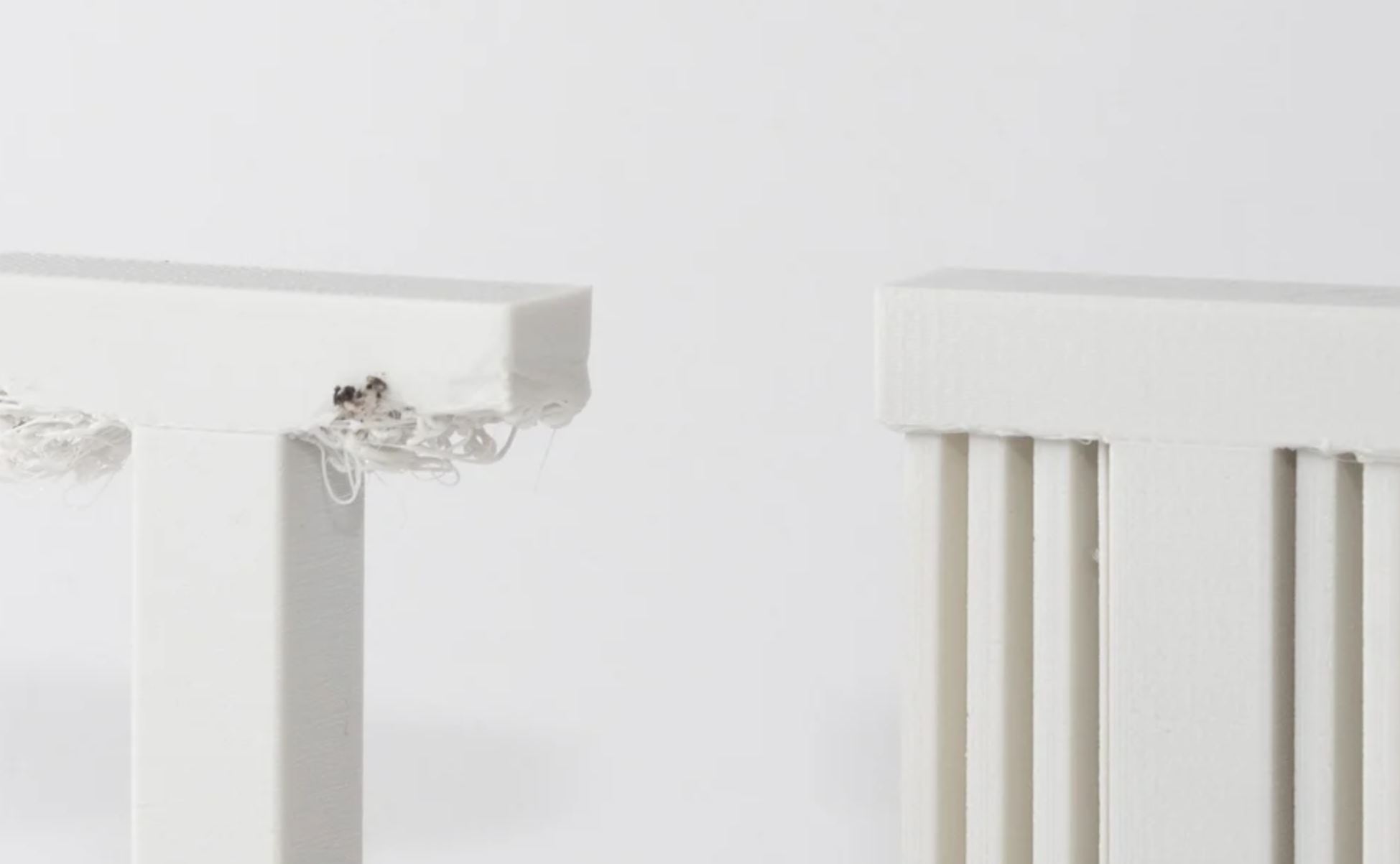
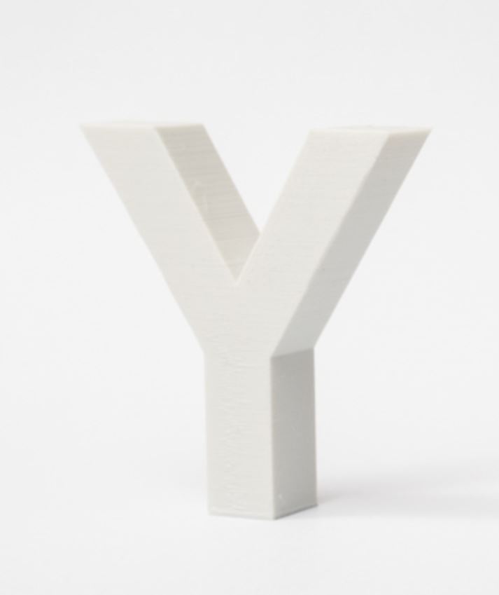
Supports are one of the most significant contributors of the quality of your print, for better or worse. Since 3D printers cannot defy gravity, most models with any geometry suspended in mid-air will require some form of support structure to ensure a successful print. However, since support structures will make contact with your model, surface scars will form at these points of contact, and enabling supports for a print that does not require them will lead to worse quality for no benefit. Using supports when they aren't necessary also leads to wasted plastic, and more time wasted removing them afterwards. Thus, being able to recognize when supports AREN'T required, and knowing what settings to use if they ARE required are essential skills for a 3D printing enthusiast!
Overhangs
Imagine 3D printing the capital letter "T" in an upright orientation. This would be referred to as an "overhang," as a portion of the "T" overhangs from either the left or right sides of the letter. Since the 3D printer isn't capable of laying down flat and even layers of plastic in midair, this print would most likely fail or result in "stringy" quality on the overhanging surfaces. A "T-Overhang" would be an example of an overhang that would require the use of supports.
However, not all overhangs require supports, imagine 3D printing the capital letter "Y" in an upright orientation. This would also be referred to as an overhang, since the top of the "Y" will overhang from either the left or right sides. One may think because of the overhangs, supports would be required, however, printing the "Y" without any supports would result in a successful print. Since the overhanging portions of the "Y" gradually slope upwards, and the 3D printers operate on a layer-by-layer basis, each layer of the "overhanging portion" will be supported by the previous layer. These overhanging portions are often described with the term "overhang angle", and an overhang angle of less than 45° is usually safe to print without supports. Since the "T" has an overhang angle of 90° with the vertical, it would be considered unsafe to print without supports.
Therefore, when designing models for 3D printing, avoid "T" style overhangs, and use overhanging angles of 45° (or less) as much as possible. If you're printing a model with overhangs, try to re-orient it to minimize the amount of "T" style overhangs. For example, orienting the letter "T" so that it lays flat on the bed ensures that supports will not be required.
Bridges
Bridges are overhanging sections that are supported by two or more model sections (e.g.: the middle section of an H is a bridge). It can be possible to print bridges without the use of supports, though one should take care to optimize their printer settings (lower temperature, higher fan speed, etc.) to limit drool. Tuning a printer or adapting a slice for bridging demands a deep understanding of the fundamentals, and such, these will only be discussed in a more advanced 3D printing learning module.
Removing Supports
Removal of supports can also determine if one wants to use them. In prints using larger nozzle sizes (hotter nozzle, higher material flow), supports might be firmly fused to the model being printed. In such cases, removing supports might be extremely difficult. However, when using optimal settings, supports will be easy to remove. They typically break off with little effort. A pair of small long nose pliers can also come in very handy when removing supports.
Troubleshooting a failing print
Many things can go wrong when 3D printing. Thankfully, using recommended settings should always work well, and such, diagnosing a failing print is fairly easy. The following are a set of issues, possible causes, as well as potential fixes.
| Issue (symptom) | Possible Cause (diagnosis) | Potential Fix (cure) |
|---|---|---|
| Warping | Not enough/too much model base surface contact to the print bed | Use a brim or a raft (adhesion)* |
| Bad adhesion | Not enough/too much model base surface contact to the print bed | Use a brim or a raft (adhesion) |
| Uneven print bed/Bed too far from nozzle at initial layer | Relevel the buildplate | |
| No extrusion | No filament | Replace filament spool |
| Filament clog | Keep in mind that it is uncommon that this is the actual cause of lack of extrusion. Ask a Makerspace employee to assist with further diagnosis | |
| Underextrusion | The forwarding mechanism (gearbox) ground through the filament | Move the filament out of the forwarding mechanism. Use the change material feature to speed up the removal. While the mechanism is whirring to remove the material, pull slightly on the filament, at the back of the printer for the mechanism to grab. Break the filament clean off at the section where the filament was ground, clean up the end by cutting it off. Re-forward the material into the printer, making sure the right material is chosen in the menu. |
| Wet (very brittle) filament | Remove wet section of the filament (0.25 to 0.5m length) and re-load | |
| Filament clog | Keep in mind that it is uncommon that this is the actual cause of lack of extrusion. Ask a Makerspace employee to assist with further diagnosis | |
| Print not level | Model not well seated on bed (in slicer) | Use the snap to bed feature in your slicer (when available), add a brim to preview which flat sections are well seated on the bed |
| Drooling | No supports when needed | Add supports |
*Though it may be counterintuitive to increase part base area with a brim when the issue is that the base surface is too large, using a brim permits leads to reduced warping. If warping does occur, the brim acts as a sacrificial piece (reducing the impact to the part with little to no negative impact on print time or post processing time).
What not to print on a 3D printer
3D printers are extremely versatile and wonderful for fast prototyping, but there are things that you should not print on a 3D printer, either because there is a better way to do it, or because the features you are trying to print are simply not going to come out well.
Machine Threads
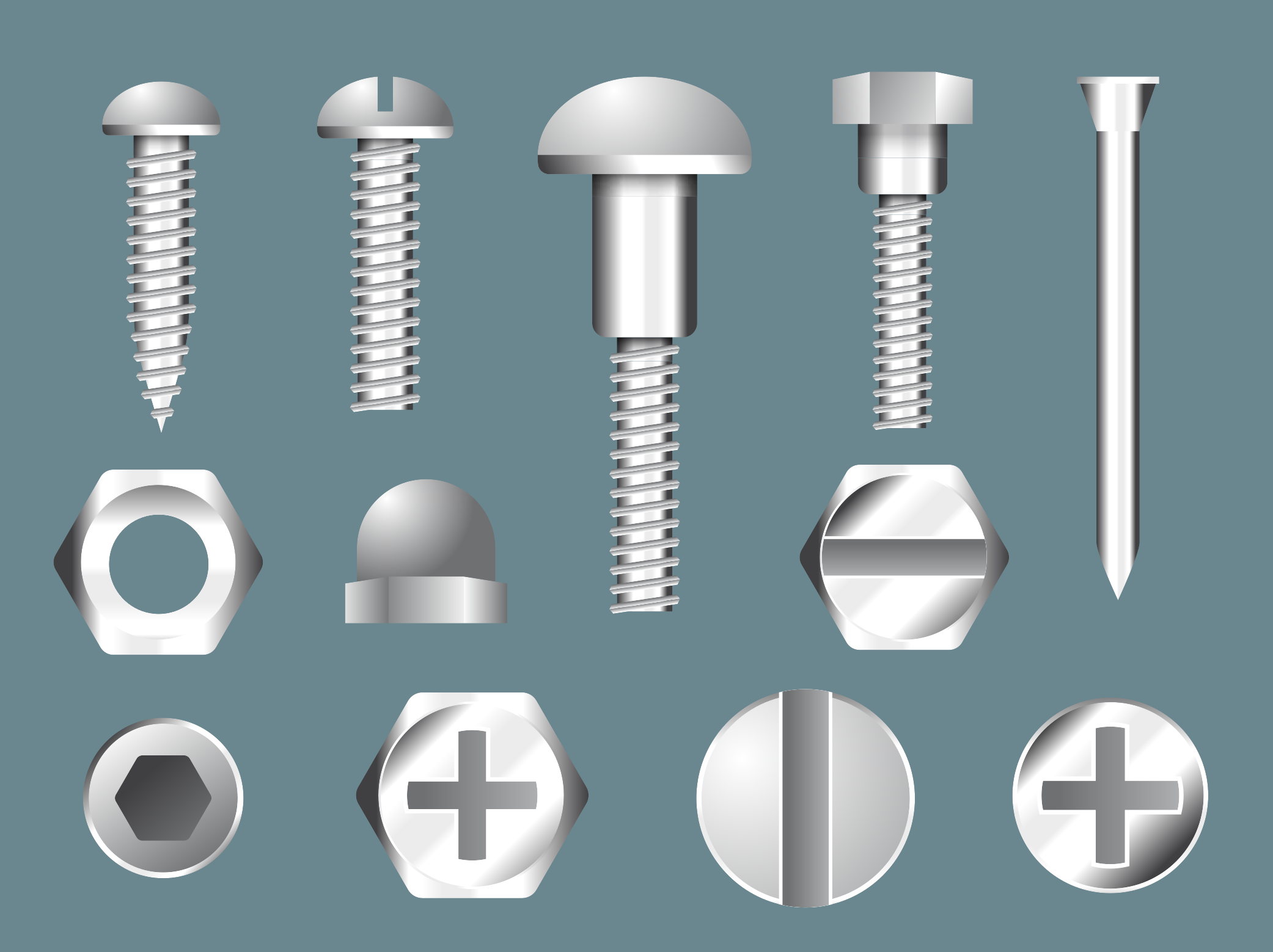
Machine threads are probably the last thing you want to try to 3D print. The threads are way too small to come out well. Your threads will not look nice, and your screws will not thread in properly. If you really need a machine thread in your design (which is typical of designs), consider using a heat insert (single or double vane depending on the pull-out resistance you're looking for) or an expanding insert for plastic (though expanding inserts might put too much pressure on the part and split it). Inserts might be available in the Makerstore but otherwise are available at the previously linked pages. Make sure to specify the holes in your designs as per the datasheet provided. A design guide is provided in the Advanced CAD modeling for 3D printing page for convenience. Adhering to this design guide will greatly simplify the heat insert installation process.
Electronics Enclosures
We of course have all grow up surrounded by plastics as the main enclosure material. This is not wrong. When enclosing electronics, an insulating material is definitely recommended. Injection molded enclosures are also much more suitable for production runs on products. 3D printed, however, an electronics enclosure can end up being a waste of time. The prints will take ages to complete, and chances are the 8 hours you are allowed for a print at the Makerspace will not be sufficient. Designers should notice that larger electronics enclosures often have large flat sections. Large flat sections are so much easier to laser cut than to 3D print. Consider cutting out large flat sections from your designs are replacing them with a laser cut panels. Otherwise, consider laser cutting the whole enclosure! See the Laser Cutting pages for design resources.
References
- ↑ Gringer (Wikipedia User, 2018). Fused Filament Fabrication. Wikipedia. Accessed 2022-07-25 at https://en.wikipedia.org/wiki/Fused_filament_fabrication
- ↑ Redwood, Ben (2022). How does part orientation affect a 3D print? Hubs, a Protolabs company. Accessed on 12/05/2022 at https://www.hubs.com/knowledge-base/how-does-part-orientation-affect-3d-print/
- ↑ B3D Online (2022). FFF/FDM 3D Print 101-Layer Height, Infill & Support. Accessed 2022/05/16 at https://www.b3d-online.com/blog-news/ffffdm-3d-print-101-layer-height-infill-support
- ↑ Modified from Ultimaker B.V. Ultimaker 2 User Manual. Consulted on 2022/05/16 at https://support.ultimaker.com/hc/en-us/articles/360011955399-The-Ultimaker-2-user-manual
- ↑ Alvarez C, Kenny L, Lagos C, Rodrigo F, & Aizpun, Miguel. (2016). Investigating the influence of infill percentage on the mechanical properties of fused deposition modelled ABS parts. Ingeniería e Investigación, 36(3), 110-116. Available online: http://www.scielo.org.co/scielo.php?script=sci_arttext&pid=S0120-56092016000300015
- ↑ Modified from content accessible through https://www.freepik.com/vectors/elements.
- ↑ https://www.mcmaster.com/91290A150/
- ↑ https://www.mcmaster.com/90593A003/
- ↑ https://www.fastenal.com/product/details/39022
- ↑ https://www.fastenal.com/product/details/40146
