Digital technologies/3D printing/3D printing- Intermediate
This page will focus on intermediate 3D printing skills. You should be familiar with 3D Printing- Beginner before continuing.
Types of printers
Printers
There are many different types of 3D printers that exist. Theses printers can be primarily categorized into 7 categories:
- Material Extrusion
- Vat Polymerization
- Powder Bed Fusion
- Material Jetting
- Binder Jetting
- Directed Energy Deposition
- Sheet Lamination
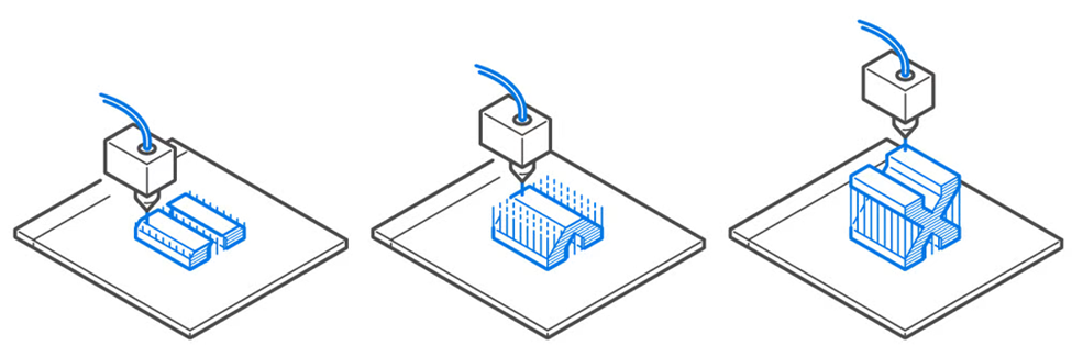
Material extrusion is the most commonly used 3D printing method. It refers to 3D printing where the material is extruded through a nozzle on to a build plate in a pre-determined path and the material solidifies into a solid object. Typically, the material used are plastic such as PLA and ABS. It is usually the most cost-effective 3D printing option, however, it does not provide the best dimensional accuracy. The material properties of printed object is also not that great compared to other methods. The FDM printers in Makerspace are a good example of material extrusion 3D printing.
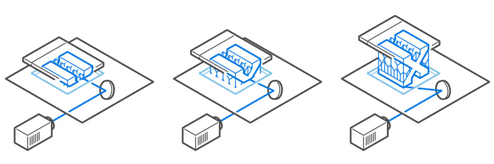
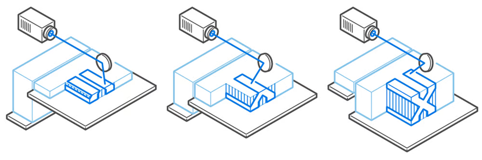
Vat polymerization also known as resin 3D printing uses a light source to selective cure photopolymer resin in a vat. The build plate is moved vertically once the first layer of the print is cured. This is done layer by layer until the entire object is built. After the printing process, the object is cleaned of the remaining liquid resin and cured to ensure the mechanical properties of the part. The most common form of vat polymerization is stereolithography (SLA).
SLA is the oldest form of 3D printing technology. SLA printers use mirrors known as galvanometers with one on the X-axis and one on the Y-axis. The galvanometers aim the laser beams across a vat of resin, curing and solidifying a cross-section of the object inside the building area. Resin 3D printing allows for smoother surface finish with finer feature details. Makerspace offers resin 3D printing through Elegoo printers.
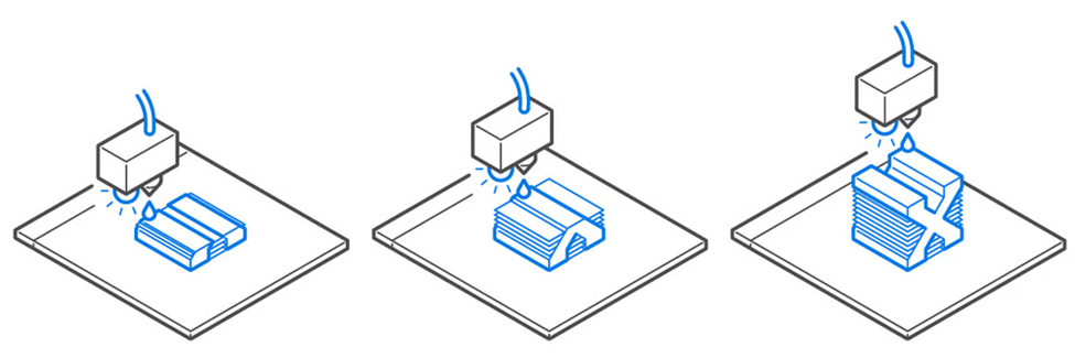
Other forms of resin printing include digital light processing (DLP) and liquid crystal display (LCD). DLP 3D printing uses a digital light projector instead of a laser beam like SLA printers. The digital projector screen flashes an image of a layer across the platform. This cures all points simultaneously. LED screens or a UV source is used to project light onto the resin. This light is directed to the build surface by a digital micromirror device (DMD). LCD 3D printing is also called masked stereolithography (MSLA) is similar to DLP above. Instead of a DMD, LCD printers uses an LCD screen. LCD is a newer technology designed to be an affordable alternative to DLP and stereolithography. It cures an entire layer of resin at once using an array of ultraviolet LED as a light source. It uses an LCD to selective mask UV light so that only selected areas are cured.
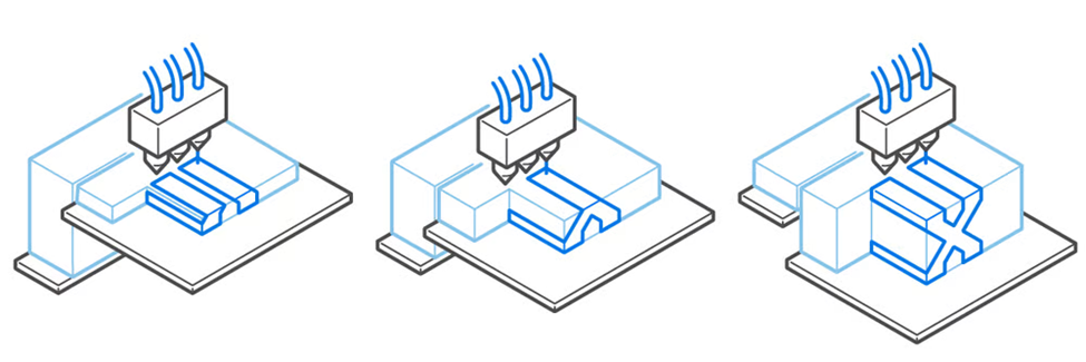
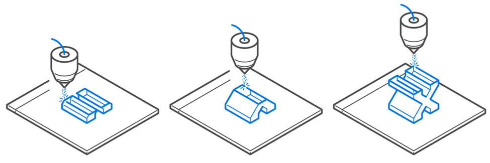
Powder bed fusion printers spread a thin layer of powdered material over a print bed which is melted (typically by a laser). This process is repeated with the powder layer fusing at specific points with the previous layer until the object is completed. The final product is encased and supported in unfused powder. This method is great for parts with complex geometries however it has a higher machine cost with higher material cost. It often results in slower build rates.
Material jetting involves tiny droplets of material that are deposited onto the build plate. The droplets are cured when exposed to light. This process is repeated layer by layer. This process allows for different materials to be printed in the same object. It can create textured surface finish. However, the process has limited materials and often have weaker mechanical properties with a higher process cost.
Binder jetting uses a liquid bonding agent that selectively binds layers of powder together. The printer nozzle will pass over the print bed and selective deposit droplets of binding agent on the powder layer. This process combines powder bed fusion and material jetting.
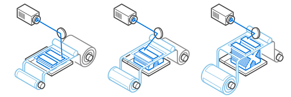
Directed energy deposition is a process where material is fed and fused at the same time as it is deposited. This is typically only performed on metal material. It is very similar to welding. This process is often used to repair or add features to metal objects by printing on pre-existing metal objects.
Sheet lamination is technically considered a form of 3D printing. However, it differs significantly from the other methods mentioned above. It stacks and laminates sheets of very thin material together to produce a 3D object. The stack can also be cut mechanically or by lasers to create the final shape. There are many ways fuse the material layers such as heat and sound. Since material is fused together then cut, this way of 3D printing generates much more waste than other technology.
Each brand of printer will have a different slicer and way of starting the prints which is explained in the following sections.
Slicers
There are many different slicers that can be used. Typically each 3D printer company will have its own 3D slicer software. For example, within Makerspace Ultimaker Cura is the typical slicer used for the Ultimaker printers. For more information about each slicer click on the "More Info" button under each printer below.
Our Printers
The following are the printers available for use at the Makerspaceː
| Slicer | Cura |
|---|---|
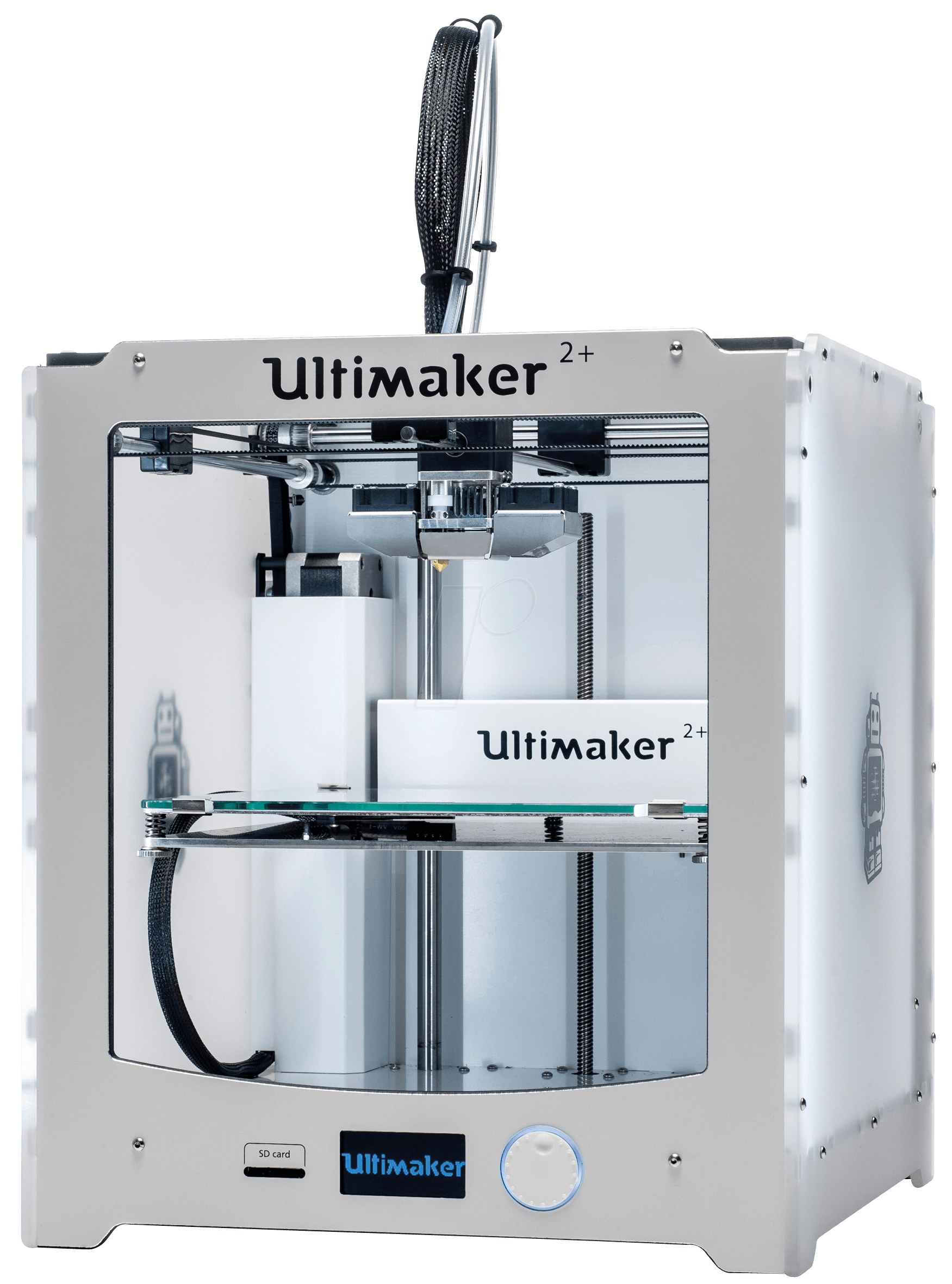
| Build Volume | 223 × 223 × 205 mm |
| Compatible materials | PLA, ABS, Flexible, etc |
| Minimum Layer Height | 0.06 mm |
| Heated Build Plate | Yes |
| More Information | Ultimaker 2+ |
| Slicer | Cura |
|---|---|
| Build Volume | 215 × 215 × 200 mm |
| Compatible materials | PLA, PVA, Flexible, etc |
| Minimum Layer Height | 0.02 mm |
| Heated Build Plate | Yes |
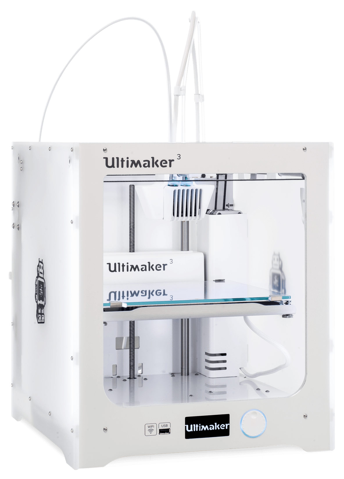
| More Information | Ultimaker 3 |
| Slicer | MakerBot Print |
|---|---|
| Build Volume | 285 × 153 × 155 mm |
| Compatible materials | PLA |
| Minimum Layer Height | 0.1 mm |
| Heated Build Plate | No |
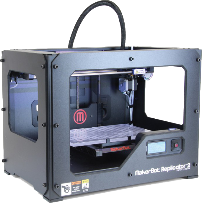
| More Information | MakerBot Replicator 2 |
| Slicer | DigiLab 3D |
|---|---|
| Build Volume | 230 × 150 × 140 mm |
| Compatible materials | PLA |
| Minimum Layer Height | 0.1 mm |
| Heated Build Plate | No |
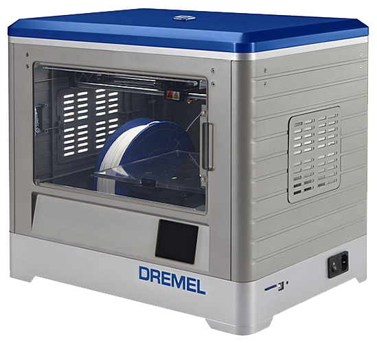
| More Information | Dremel 3D20 |
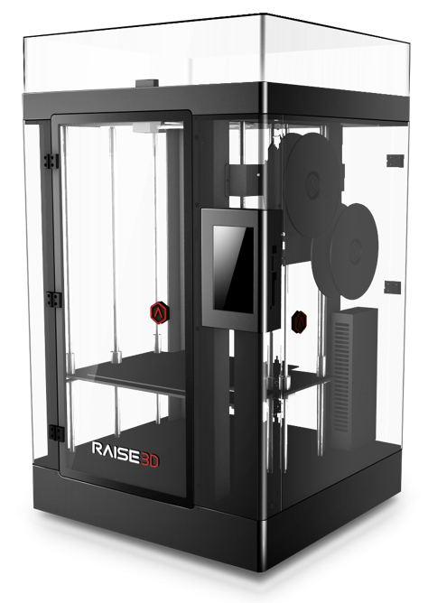
| Slicer | ideaMaker |
|---|---|
| Build Volume | 305 × 305 × 605 mm |
| Compatible materials | PLA, ABS, PVA, Flexible |
| Minimum Layer Height | 0.01 mm |
| Heated Build Plate | Yes |
| More Information | Raise3D N2 Plus |
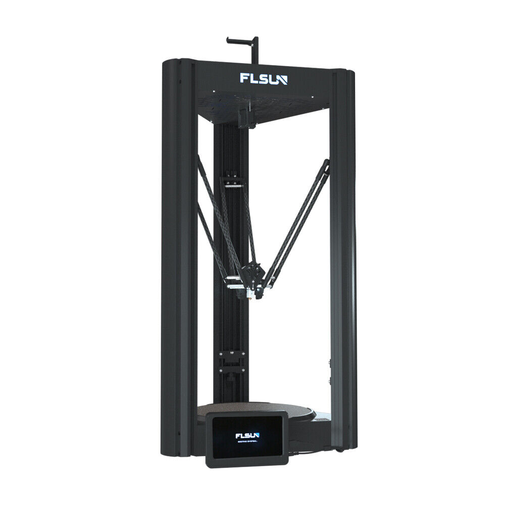
| Slicer | Cura |
|---|---|
| Build Volume | 300 × 300 × 410 mm |
| Compatible materials | PLA, ABS, Flexible, etc |
| Minimum Layer Height | 0.05 mm |
| Heated Build Plate | Yes |
| More Information | FLsun v400 |
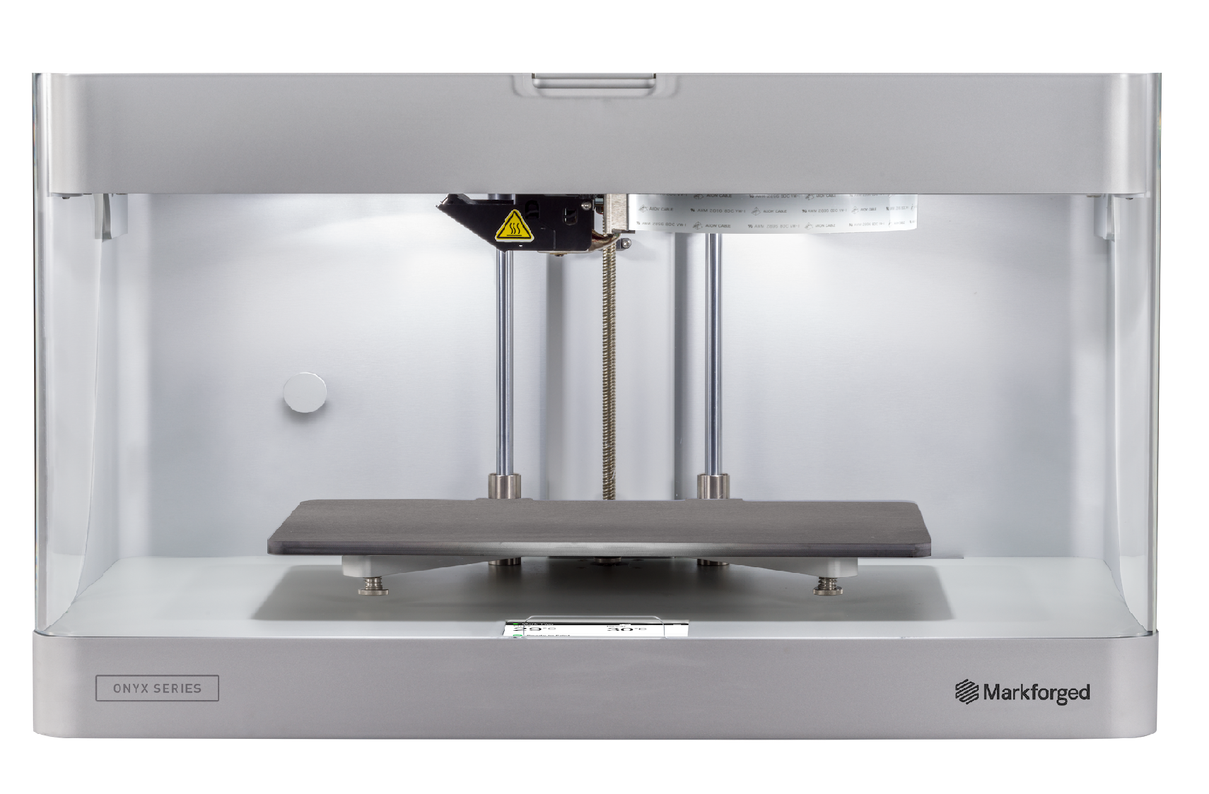
| Slicer | Eiger |
|---|---|
| Build Volume | 320 × 132 × 154 mm |
| Compatible materials | Nylon, Onyx, Carbon Fiber, Fiberglass, Kevlar |
| Minimum Layer Height | 0.1 mm |
| Heated Build Plate | No |
| More Information | Markforged Mark Two |
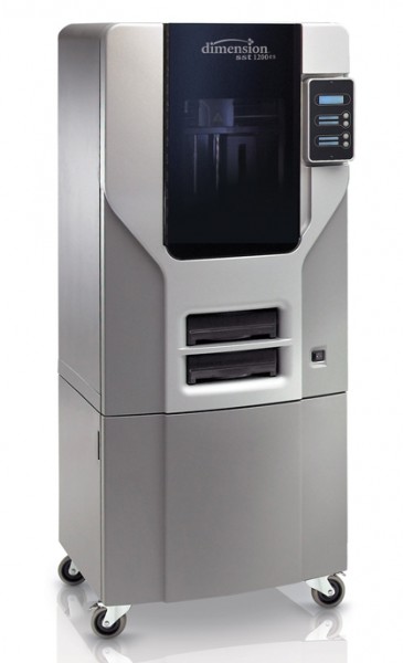
| Slicer | GrabCAD Print |
|---|---|
| Build Volume | 254 × 254 × 305 mm |
| Compatible materials | ABS, Soluble support |
| Minimum Layer Height | 0.254 mm |
| Heated Build Plate | Yes |
| More Information | Stratasys Dimension SST 1200es |
| Slicer | GrabCAD Print |
|---|---|
| Build Volume | 254 × 254 × 254 mm |
| Compatible materials | PLA, ABS, ASA, TPU, Soluble support |
| Minimum Layer Height | 0.127 mm |
| Heated Build Plate | Yes |
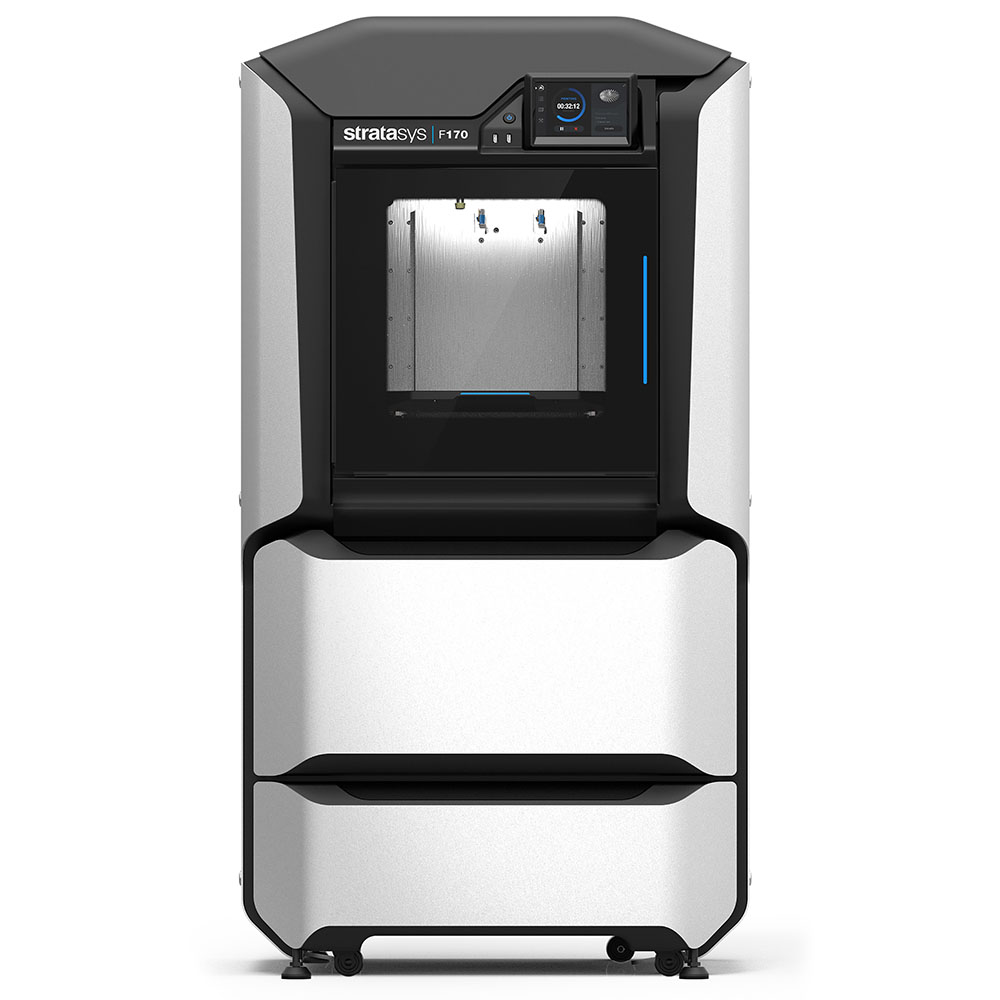
| More Information | Stratasys F170 |
| Slicer | ChituBox |
|---|---|
| Build Volume | 218.88 × 123.12 × 250 mm |
| Compatible materials | Standard, ABS-like, rubber, etc |
| Minimum Layer Height | 0.01 mm |
| Heated Build Plate | No |
| More Information | Elegoo Saturn 2 8k |
Custom Slicer Settings as an Intermediate User
In the beginner section of 3D printing, basic slicer settings such as layer height, infill percentage, supports and adhesion haves been introduced. In this section, more advanced settings such as print speed, nozzle size, adhesion type (…etc) will be discussed.
In order to start customizing your slicer settings, you will have to access the setting menu. To do so, make sure you are in the prepare view. Click on the dropdown triangle in the top right hand corner. You will be shown the recommended settings automatically. Then select the custom button at the bottom to further customize your options.
How to Modify Parameters
Layer Height
Layer heights are generally changed to increase printing speed. A larger layer height means a faster print as the printer can print less layers to achieve the final height. However, increasing layer height will decrease the resolution and quality of the print. Therefore, increasing layer height should only be done on larger prints without fine details. It is recommended to keep the layer height between 25%-75% of the nozzle diameter and a 50% nozzle diameter is generally what is used as the layer height. If the layer height is too low, it can result in the plastic being pushed back into the nozzle creating a blockage. If the layer height is too high, it can be difficult for the layers to stick to each other.
Within the 3D printing community, there are discussions of “the magic number”. This refers to the increments of layer heights that provides the most efficient prints. It considers the mechanical properties of the printer stepper motors. It takes the ‘steps’ that the stepper motor travel in as layer height intervals. So the layer heights are set as multiples of these ‘steps’. In the case of the Ultimaker printers, the magic number is 0.04mm.
Walls
There are many things that can be customized within the wall settings. Cura also allows the user to customize wall line count which is the number of passes the nozzle will perform for the walls. Changing this value will automatically change the value for wall thickness. However, users can change the value manually as well. Typical values for wall thickness are chosen depending on the purpose of the print and the material used. Generally the default values of 0.8mm-1.6mm (3-4 wall lines) should be sufficient for typical prints. The wall thickness should be set at multiples of nozzle size for ideal printing. If the strength of the part is crucial, use larger values for wall thickness such as 2-3mm. If the model has fine details where strength is not required, wall thickness can be reduced to 0.4mm. The user can also customize horizontal expansion value. This setting is used to compensate for the horizontal shrinkage of the print. It will add the input value to either side of the XY plane. This option is typically enabled when printing material that will shrink when cooled and dimensional accuracy is required. It is unnecessary for PLA printing.
Top/Bottom
Top and bottom layers are the layers at the top and bottom of the 3D model. In Cura, top and bottom thickness can be adjusted and customized. Similarly to wall thickness, this can be adjusted by the number of layers or by the thickness value. The thicker the layers are the stronger the model would be. The thicker the layers are will also increase the watertightness of the model. However, this means that the model will use more material and take a longer time to print. It is usually recommended that the Top/Bottom Layer Thickness should be at least 1-1.2mm thick, ensure that it is a multiple of the layer height which will prevent print defects.
Infill
In the previous section, the recommended infill percentage was discussed. In this section, infill pattern can also be customized. There are 14 different patterns to choose from.
Lightning, lines, zig-zag are best used to print models and figurines with a typical 0-15% infill. This is because they don’t require the prints to have a high strength as they are not subjected to rough handling or put under stress. The three patterns result in the fastest prints. Grid, triangles and tri-hexagon are used for typical 3D prints with infill density for 15-50%. It is suitable for prints with low stress. Choosing these patterns may increase print time by up to 25% when compared to lines. If the print is functional such as a shelf bracket that requires strength in multiple directions, cubic, cubic subdivision, quarter cubic, octet and gyroid are great options. Many times these patterns are also chosen for infill densities smaller than 50% for their aesthetics. Concentric, cross and cross 3D are often chosen for flexible filament prints.
Print Speed
The basic print speed settings control the speed of all stages of the printing process. However, the speed of each stage can be further customized in the advanced settings. This includes infill speed, wall speed, travel speed etc. The ways in which the print speed will affect the final print are not always obvious. If the print speed is set too fast, the printer might not be able to dispense enough material through its nozzle per unit of time to fill the desired volume with the required amount of material. This can lead to bad adhesion between layers or even a complete lack of adhesion to layers. Therefore, it is important to consider the ratio between layer height and layer speed. The Ultimaker 2+ in Makerspace are capable of achieving speeds of up to 300mm/s. However, this is not recommended as it significantly reduces the quality of the print. Realistically it is possible to print reliably using about 70-80mm/s depending on the material and the model.
The ways in which the print speed will affect the final print are not always obvious. If the print speed is too high, the printer might not be able to dispense enough material through its nozzle per unit of time to fill the desired volume with the required amount of material. This can lead to bad adhesion between layers or even a complete lack of adhesion to layers. The ratio of layer height to layer speed (i.e.: material outflow through the nozzle) should therefore always be considered when FDM printing (the exact subject though being more of an intermediate subject). When making parts that will bear loads, print speeds are increasingly important as layer adhesion becomes an important factor in the strength of the final part, so much so that parts may be annealed (uniformly re-heated through a controlled process) to obtain better properties across layers.[1]
Travel
Retraction is enabled when the printer has to travel between two printed parts. Without retraction, the extruded material will hang between the parts. Enabling retraction prevents the “stringing” of the extruded material which will result in a cleaner model. Enabling Z-hop when retracted will move the build plate down by the set value when retraction is performed. This will prevent the nozzle from hitting the object or damaging the print surface. However, adding additional nozzle travel will increase the print time.
Cooling
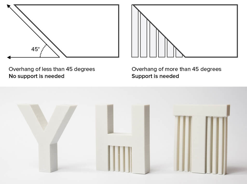
The fans allow the material to cool properly before the next layer is printed. By enabling the fans, it will allow layers with short layer time and those with bridges/overhangs to have a better print quality. Fan speed can be adjusted based on the needs of the print. A higher print speed means better cooling and reduces the oozing of the material.
Supports
Supports were introduced in the beginner module of 3D printing. In this section, further details of support will be explained. Typically supports are used when there is an overhang in the design. There are two options when implementing supports, support structures need to touch the build platform or touch the top of the model. The default settings have the supports touching the build plate only. However, this can be changed to have supports touching everywhere. This can be useful as it increases the support area but it can be extremely difficult to remove supports that are on the printed objects. The support overhang angle can also be changed. Generally, supports are printed for overhang greater than 60 degrees. If the object is printed at a slow speed, the overhang angle might need to be lowered than if printing at a higher speed. Your design can also be altered to reduce supports. Filet and chamfer sharp angles which will reduce overhang angles and increase the quality of the print. You can also consider splitting your print into multiple parts to be assembled afterwards.
Adhesion

There are three types of adhesion, skirt, brim and raft. Brim adds a single layer flat area around the base of the print model which prevents warping. This is the default adhesion type. The brim is connected to the model making the bottom surface area bigger. It not only increases the adhesion of the model to the build plate, but it also prevents the corners of the model from curling. Materials with high potential for shrinking such as ABS will benefit from a brim. Models with a large base or a thin bottom should also use a brim adhesion. As raft adhesion adds a thick grid with a roof between the model and the build plate. This is typically used when the bottom surface of a model is not completely flat or has little area to adhere to the build plate. A skirt is a line printed around the model on the first layer. It is typically not used to help the print adhere but used to prime the nozzle and check for bed leveling.
Dual Colour and Dual Extrusion
Dual colour prints refer to a technique that can print multiple colours on one model using one nozzle head. This is achieved by switching the filament during the printing process. Dual extrusion refers to printing a model with 2 nozzles to extrude two different filaments. This will allow for mixing colours, gradients, or patterns. It can also print models using two different materials for different parts of the object for complex geometries that would otherwise be difficult to achieve.
Dual colour prints are achievable using the Ultimaker 2+ printers. In order to change the colour during the print, a script is added to the g-code telling the printer to stop the print at a certain instance. This is done during the slicing process in Cura.
- Click on “Extensions” in the top menu bar.
- Select “Post-processing” -> “Modify g-code”.
- Click on “Add a script”
- Select “Pause at height”
At this point, there will be many different settings to modify. First, determine if you would like to pause at a height value (mm) or at a layer number. Choosing a layer number would be a simpler option in ensuring that the print ends when a full layer is completed. The layer number can be seen in the “Preview” mode on Cura. The model can then be sliced like normal. Once the print stops, the material can be changed (ask the staff) to complete the print in a different colour.
Dual extrusion prints are possible using the Ultimaker 3 or Raise printers in MakersSpace. To do so with the Ultimaker, two separate 3D models are needed. If they are part of the same model, they will be merged together in Cura. Ensure that the printer selected is Ultimaker 3. The printer can be added using “Add printer” button. Open both models in Cura and set the print core and the materials. This can be done through the printing options beside the printer selection. Both print cores should be set at AA .4. The material is set to PLA by default but it can be changed to the material of our choice. There is no need to change the colour of the filament on Cura as it will be determined by the filament that is loaded in the printers. By default, both models will be set to print with core 1. To change the print core, select the model then select per model settings and print model with print core 2. After the print core, merge the two models together. Select both models by holding shift while left clicking on both parts. Both models should thenm be highlighted in blue. Then, right click and select “Merge Models”. The two models will then become a single model. At which point, you can adjust the printer settings like a regular single extrusion print. If you would like to customize the settings for one print core, the printer settings need to be assigned in custom model.
Print Orientation
Print orientation is crucial to the success of the 3D model print. It heavily influences the speed and quality of the result. There are many different factors to consider when choosing how to orient your print.
Understand the build volume of the printer. The print needs to be oriented in a way that it will physically fit in the printer when printed. If the print is too big, the model can be divided into multiple parts to be printed separately. The Ultimaker 2+ printers have a build volume of 223 x 223 x 205mm.
To determine which face of your design should face down on the build plate, it is important to choose the best face for stability and bed adhesion. This is typically a face that is large enough to provide stability and a flat surface to minimize the need for build plate adhesion.
It is also important to consider the mechanical stresses that your part will experience. Orient the part so that the direction of minimum applied stress is along the build direction (vertical). The build direction is typically weaker since it relies on the bond strength between layers rather than the strength of the material. The print should also be oriented to minimize print time and supports used. These two factors are connected as the more supports needed, the longer the print will be.
Post-Processing 3D prints
There are a number of post processing possibilities with 3D printed models. The options available are dependent on the material used. In this section, post-processing possibilities for PLA that are available in the Makerspace will be explored. The video below will explain the basics of post-processing. Everything used in the video is available at the finishing station in the Makerspace.
The most basic post-processing procedure is support removal. The Ultimaker 2+ printers in Makerspace are single extruder printers which means the supports are printed using the same material as the main model. Typically, the supports are easily removed by breaking them off the printed model. However, when supports are placed in tight corners or hard to reach places, additional tools such as pliers will be needed to remove the material. Dual extruder printers will allow you to print the supports with a different soluble material than the main part. This means the difficult to remove supports can be dissolved away by soaking it in another liquid.
Another basic procedure is sanding. 3D printed parts will often have rough surfaces from the layers. Sanding is the easiest way to create a smooth surface. At the finishing station, there are sandpaper of different grit sizes to sand down your model. There are also files at the station for edges and holes. It is important to sand the surfaces in circular motions to ensure the aesthetics of the model.
Gluing the model is one of the most common post-processing options to attach parts together. There are many glue options available at the Makerspace, including super glue and hot glue. Hot glue is easy to use but it will leave a visible gap as 2-3mm of glue is needed to secure the parts together. Hot glue is also not very strong. Super glue is a good option for a seamless seal that cures fast.
Painting is one of the most common finishing processes. The model needs to be primed first before being painted. The model should be sanded with a low and then medium grit sandpaper. Prime the model with a coat of primer paint. Once everything is dry, you can start painting your model with other colors. Acrylic paint and paintbrushes are available to use at Makerspace.
Bed Levelling, Filament Change
Bed Levelling
If the printer is not printing properly (especially if the issue is noticeable on the very first layers of the print, where a difference in the layer height is noticeable), the build plate level may need to be adjusted. For minor adjustments, this can be done by using the three knobs (thumb screws) on the underside of the plate. For more major adjustments (>1mm), the build plate should be leveled through the printer’s onboard software by going to Maintenance→Build Plate, and following the onscreen instructions. If unsure, always use the latter method. The calibration cards needed are at the finishing station. However, in Makerspace, bed levelling should only be performed by the staff.
Filament Change
To change the filament on an Ultimaker 2+ printer, go to Material→Change in the printer’s user interface and follow the onscreen instructions. If ever the filament has almost run out, or if you desire to change the color of a print midway, you may navigate to Pause→Change Material and following the onscreen instructions. If changing mid-way, it is recommended that the older filament be completely purged from the nozzle using the new filament. Otherwise, the result will not be good. Again, within the Makerspace, this should only be done by the staff working.
Selecting Nozzle Sizes
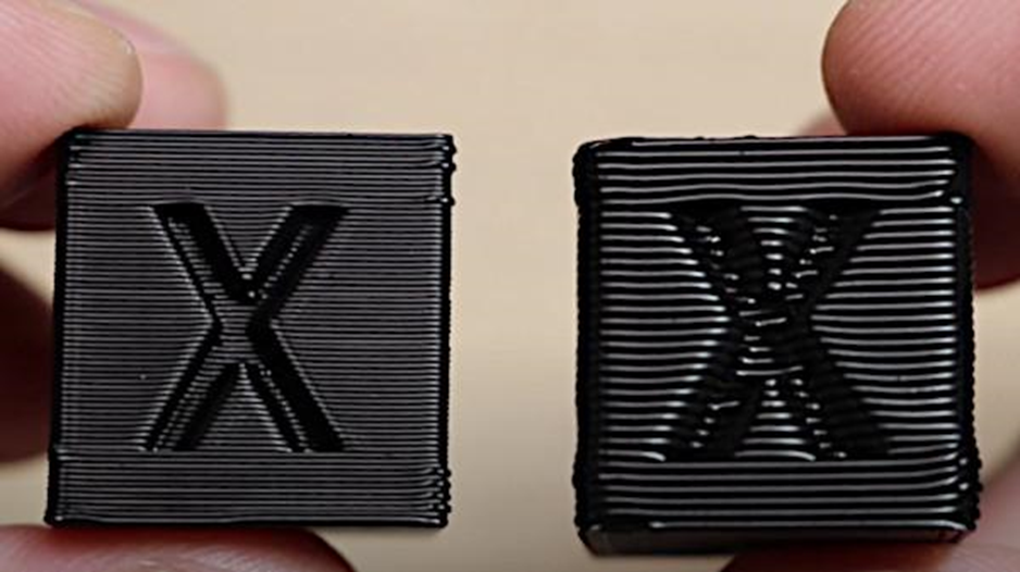
Nozzle size is the first decision to make when 3D printing. Within Makerspace, there are four options of nozzle size using the Ultimaker 2+, 0.25mm, 0.4mm, 0.6mm, and 0.8mm. Choosing between the options depends on the fine details of the model and the print speed required.
- A smaller nozzle size will allow for finer details and better dimension accuracy. However, it will also take longer to print the model.
- A larger nozzle can provide faster print time and also create stronger prints.
- A smaller nozzle diameter can cause it to be more difficult to print with overhangs as each layer has less width to adhere to the next one.
- However, with a smaller nozzle, the supports are easier to remove as the printer will use less material for supports making it easier to break away.
- A larger nozzle is able to print with less infill as the walls would be thicker to ensure strength.
Troubleshooting
https://www.youtube.com/watch?v=R-CMotQ-nqI&t=249s
| Issue (symptom) | Possible Cause (diagnosis) | Potential Fix (cure) |
| Warping | Not enough/too much model base surface contact to the print bed | Add build plate adhesion such as a brim or a raft. Refer to adhesion section for further explanation. |
| Bad adhesion | Dirty build plate | Clean off the build plate first. Debris and oils from your fingers can cause difficulties for the material to stick. |
| Not enough/too much model base surface contact to the print bed | Add build plate adhesion such as a brim or a raft. | |
| Uneven print bed/Bed too far from nozzle at initial layer | This is the least likely possibility. Relevel the build plate. Ask a Makerspace staff for more details. | |
| No extrusion | No filament | Replace filament spool. Ask a Makerspace staff to replace the filament spool. |
| Filament clog | Keep in mind that it is uncommon that this is the actual cause of lack of extrusion. Ask a Makerspace employee to assist with further diagnosis. | |
| Underextrusion | The forwarding mechanism (gearbox) ground through the filament | Move the filament out of the forwarding mechanism. Use the change material feature to speed up the removal. While the mechanism is whirring to remove the material, pull slightly on the filament, at the back of the printer for the mechanism to grab. Break the filament clean off at the section where the filament was ground, clean up the end by cutting it off. Re-forward the material into the printer, making sure the right material is chosen in the menu. |
| Wet (very brittle) filament | Remove wet section of the filament (0.25 to 0.5m length) and re-load. Ask a Makerspace staff for further support. | |
| Filament clog | Keep in mind that it is uncommon that this is the actual cause of lack of extrusion. Ask a Makerspace employee to assist with further diagnosis. | |
| Print not level | Model not well seated on bed (in slicer) | Use the snap to bed feature in your slicer (when available), add a brim to preview which flat sections are well seated on the bed |
| Drooling | No supports when needed | Add supports. Refer to the supports section. |
References
- ↑ Agnieszka Szust, Grzegorz Adamski, Using thermal annealing and salt remelting to increase tensile properties of 3D FDM prints, Engineering Failure Analysis, Volume 132, 2022, 105932, ISSN 1350-6307, https://doi.org/10.1016/j.engfailanal.2021.105932.
