Digital technologies/3D printing/3D modeling- Beginner
Tinkercad is an easy software that allows you to design 3D designs. It is easy to learn and simple to use. We strongly suggest you use this if this is your first time designing in 3D. To begin with, go to tinkercad.com and create an account. We recommend you create an Autodesk account. It's free and if you are a student, you get to have access to a bunch other Autodesk software for free!
TinkerCAD Layout
Splash Page (Designs & Projects)
The TinkerCAD splash page is very simple. On the left, you may switch design categories. This is necessary because TinkerCAD allows design of electronics circuitry and code as well as 3D modeling! For this wiki page, the relevant mode is 3D Design. On the centre of your page, you will find all your designs. It is recommended that you do not forget altogether about the navigation on the left, since chances are that you will want to create a project at some point, that will include all three design categories, for which we recommend you create a project in TinkerCAD, which can hold all design categories. This will help with keeping your workspace organised. The following buttons are useful.
- Tinkercad logo: Clicking on the Tinkercad logo with bring you back to the splash page
- LEARN: The LEARN is where you can find tutorials to help you navigate the software a little easier. There are also lessons walking you through basic projects to inspire different ideas and to practice with the software.
- GALLERY: The GALLERY is where you can see projects that other people have made visible to the public, you can copy and modify those designs or inspire yourself from them.
- Create a new design: To create a new design in Tinkercad, sign in and it will lead you to the desktop. Select the Create new design button and this will bring you to a blank workspace.
If you wish to modify a 3D model, click on the model on the main section, and then click 'Tinker this' to access the CAD Modeling page.
CAD Modeling
The design page has quite a few sections and buttons, but it all remains quite straightforward. Refer to the following image for a list of buttons. For some of the buttons, the function is self-explanatory. If you are unsure what a button does, it is likely that the function is explained in the rest of the 3D modeling beginner content.

Create a New Design
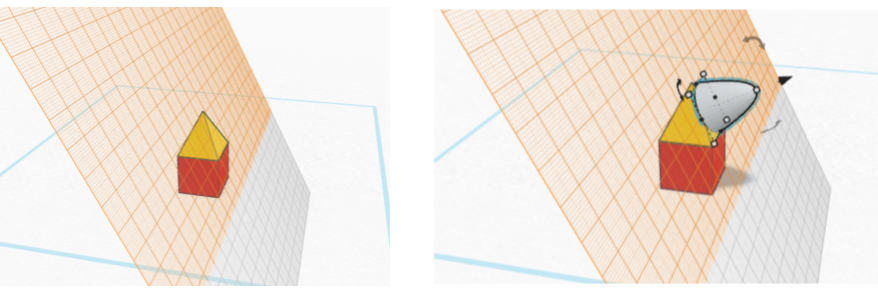
When you click “Create a new design" in the splash page, you are brought to a new window with a blue, gridded, base workplane (as illustrated in the section above). Think of the base workplane as a floor or the base of the 3D printer. You want to make sure that the part you are building is sitting on the this surface. This is where you will do your designing. There are several tools which you can use to help you design.
- Name of your design: To change the name of your design, click on the automatically generated name that is in the top left corner. This is useful to be able to find the design later and know what it is.
- View square: Drag around the square to change the viewing angle.
- View buttons: Bring the viewing angle back to home, change the zoom, switch to orthogonal view
- Show all: This will show any hidden shapes. While designing, you can choose to hide a shape. This is sometimes helpful if you want to see a piece that is under another.
- Group: Take several shapes and turn them into one shape
- Ungroup: Take a shape that is composed of several pieces, and separate them back into individual pieces.
- Align: Align several pieces
- Mirror: Mirror a component
- Import: You can also import shapes that have already been created using the Import button. You can add both 2D and 3D shapes. The file type for 2D shapes needs to be “.svg”, and the file type for 3D shapes is “.stl” or “.obj”
- Export: Download the selected object or everything on the build plate. Download it as an .stl for 3D printing and a .svg for laser cutting.
Using TinkerCAD
On the right hand side there are a series of different shapes that you can place on the your workplane (shape browser). These are your building blocks. If you click on building Basic Shapes you can select different types of shapes (or blocks).
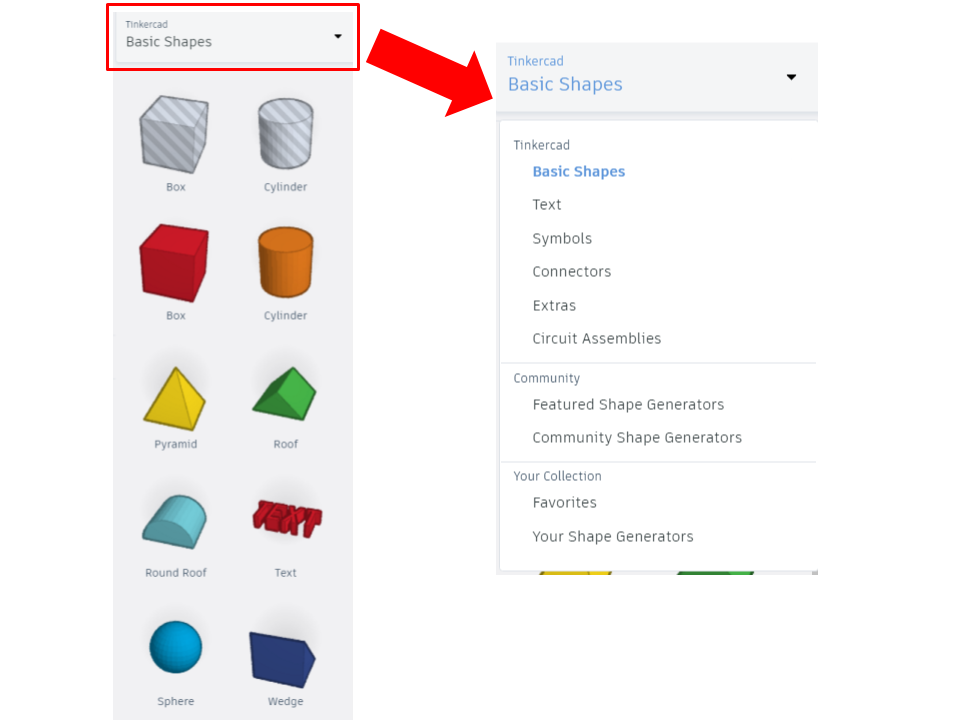
There are shapes that are registered as Holes by default. These are hatched gray and white on the shape browser. If you move them to the workplane, they will appear translucent. As you will learn, this is not very useful because any shape can be turned into a hole. For example, if you found model you liked on Tinkercad and you wanted to add a new hole.

Once you have your shape you can change the size with:
- Black cube: Change one dimension
- White cube: Change two dimensions (unless it is the shape's height)
- Curved black arrows: Rotate shape in that plane
- Black cone: Raise or lower shape
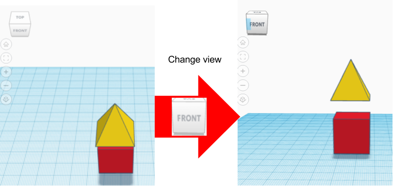
If you are putting a piece on top of another, make sure the piece is not floating. Every piece should be touching another one or be on the platform.
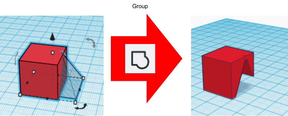
When you have a shape selected, the Shape window will open on the top right part of your workspace. This tool lets you choose if this shape is solid (coloured in the workspace) or a hole (hashed and translucent in the workspace). If you want your shape to be a hole, select the hole button and the shape should become translucent. Mind you, it will not actually take into affect until you group those two objects. The group button, found on the top right hand side of your workspace (on the top ribbon), will only be available when there is more than one shape selected. You also want to group all your shapes before downloading (exporting) a model for 3D printing (unless you are working with 2 extruder heads and you want shapes to print independently from one-another).
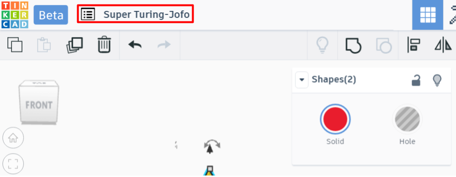
To change the name of your design, click on the automatically generated name that is in the top left corner. This is useful to be able to find the design later and know what it is. It is good practice to aim for a relevant
name.
Other Tools in TinkerCAD
Other useful tools can be found above the Tinkercad shapes menus.
Next to the group button, there is another set of useful tools, Align (L) and Flip (M).
Printing your Design
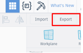
When you are done, and you want to print your new design, click Export at the top right corner.
A new window will appear. If you want to 3D print, choose which shapes you want to print (everything or only some selected shapes) and select the format .STL. If you want to laser cut a projection of the shape, select the format .SVG.
For the actual 3D printing or your part, refer to the steps found in the 3D printing pages.
Importing Models to TinkerCAD
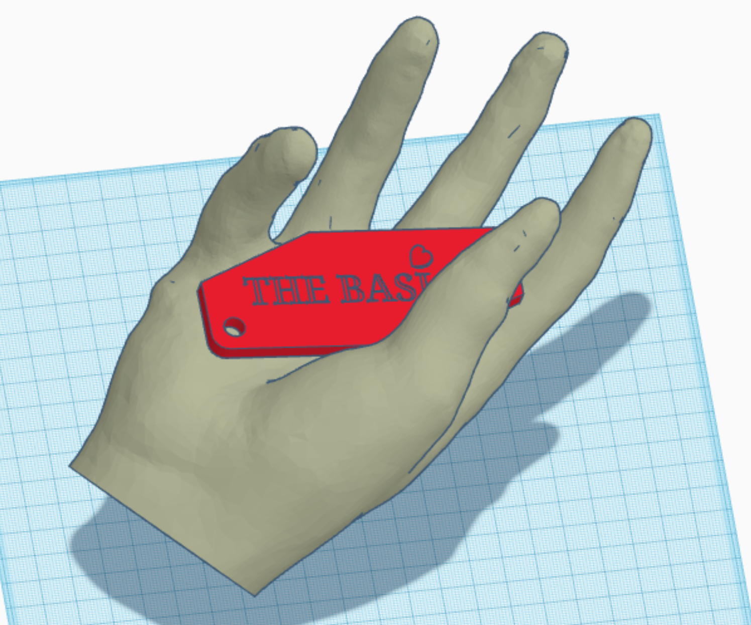
TinkerCAD can be a powerful tool for repairing or editing polygonal models (defined by triangles). Therefore, it is considered fundamental to CAD modeling in TinkerCAD to know how to import a model. You may import polygonal files (STL, OBJ, etc.) to TinkerCAD for modifications, repairs, etc. For example, if one wanted to add a label they designed to a model of a hand, this could be done in TinkerCAD. A hand is however hard to model, but there are lots of them on community CAD libraries, such as Thingiverse or GrabCAD. All that needs to be done, is for the model to be downloaded, and imported into TinkerCAD using the Import button. Once the model is imported, it will appear on the workplane. All the controls relating to shape modifications apply to the imported model! Here's an example of a composite model with the Thingiverse hand and the label from the beginner level proficiency projects example tag:
Design for 3D Printing
It is very important, while designing, to be aware of the limitations of the manufacturing method which will be used to make your design reality. Since this article focuses on 3D modeling for 3D printing, this section will only focus on those considerations relating to 3D printing. If you are unsure how 3D printing works, it is imperative that you read through the Beginner 3D Printing page on this wiki for you to understand the concepts and considerations discussed below.
Supports
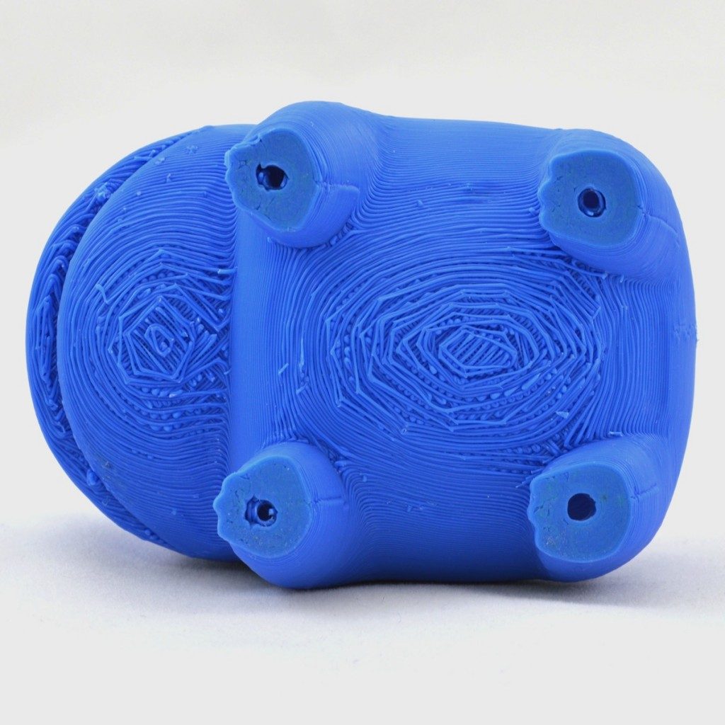
As explained in the 3D printing page, supports are sometimes required to support overhanging sections of a print. Due to the downsides of supports discussed below, it is typically better to avoid supports altogether when designing for 3D printing.
Form and surface roughness
Supports will also require post processing such as removal and sanding (if a nice smooth finish is desired). When designing for mechanical assemblies, it is important to keep in mind that supported sections might sometimes sag slightly, affecting the form of the surface being printed. Therefore, when designing (modeling), make sure that interfacing geometries (those for which the correctness of the shape, or form, is critical as it is interfacing with other parts) are not overhanging.
Hard to access supports
Support removal should always be an important consideration whenever using them. Unless of course you are fine leaving your supports in your print (in which case you might as well enclose that volume and have it be an infilled volume), you will have to remove your supports at some point, and such, you should have them be easily accessible with at the very least some snub nose pliers. While soluble supports are an option, they are practically never used in our Makerspace for prints unless the surface finish and form of the print over a support is critical. While soluble supports are cool and all, most designs can avoid containing supports that are hard or impossible to reach.

Build plate adhesion
When printing, adhesion is one of the main considerations. Make sure your design contains an adequate flat section that, if used as a base for the print, will not lead to excessive overhangs. The Thingiverse hand is a bad example the way it is positioned in Importing Models section of this article, but the way the flat section of the wrist is designed, and considering the position of the fingers not significantly overhanging (perhaps the pinkie is slightly overhanging), placed on the its flat wrist section, this hand model is expected to print properly without the use of extra adhesion features, or even supports!
Large prints
Extremely large prints cannot fit your regular build plate (or build volume). Yes, the makerspace does own 3D printers with larger build volumes, but those using them are typically charged for machine time. Instead, it can be extremely easy to split larger prints into smaller sections, and to then adhere these components together once they are all printed. The result might even look better, as sectioned parts can be oriented on the build plate to reduce the use of supports or improve adhesion.
References
- ↑ John-010 (2012). iPhone Hand. Thingiverse, accessed 2021-08-17 at https://www.thingiverse.com/thing:31331
- ↑ Simplify3D (2022). Poor Surface Above Supports. Accessed on 05-05-2022 at https://www.simplify3d.com/support/print-quality-troubleshooting/poor-surface-above-supports/
