Digital technologies/Soldering/Soldering- Beginner
What is Soldering?
Soldering is a process often used when working with electronics. It consists of melting one metal to connect two or more metal pieces. This connection not only creates an electrical connection, but it also secures a component in place.
When soldering components, be sure to heat the component to be hot enough to melt the solder and not the solder itself - this allows for better adhesion between the component and solder, the goal is to ensure that the connection between the two is as secure as it can be. The iron is not meant to be used to melt solder on to it and then wipe the solder onto the component and board.
Types of Soldering
Through-hole-technology (THT)
- Through-hole-technology (THT) soldering means to solder components that have leads that will go through holes inside a protoboard or PCB.

Surface mount device (SMD)
- Surface mount (SMD) soldering is when you will solder a component to the surface of a PCB. This type of soldering is typically used for smaller components and chips.

Safety When Soldering
- Melting solder will produce fumes and so you must always solder in well ventilated areas, this goes especially for any solder that contains lead since it can lead to respiratory irritations after extended exposure
- When Soldering be sure to wet the sponge being used in order to avoid burning it or ruining the tip of the iron
- Don’t leave the iron unsupervised and on
- Don’t touch the tip or neck of the iron
- Allow the solder and board to cool before handling
- Be sure to wait until the iron cools before storing it, in order to avoid burring or melting any thing else in its vicinity
Equipment and Materials
Types of boards
Breadboards
Breadboards are used to build temporary circuits, they allow you to plug wires into the board and prototype circuits. The holes in a breadboard are typically connected in 2 ways: the (+) bars running down the board are connected vertically and the (-) are connected in a similar way. Each horizontal row of 5 dots is connected together. The part in the middle of the board is where the connection breaks.

Protoboards
A protoboard (also known as a perfboard or stripboard or DOT PCB) is a PCB with pre-drilled holes that have square or circular copper pads. This board allows you to insert components into the holes to secure them and then the holes can be bridged together in order to connect them together and create a circuit. A protoboard typically has individual pads on the board and a stripboard will have many pads already connected together.

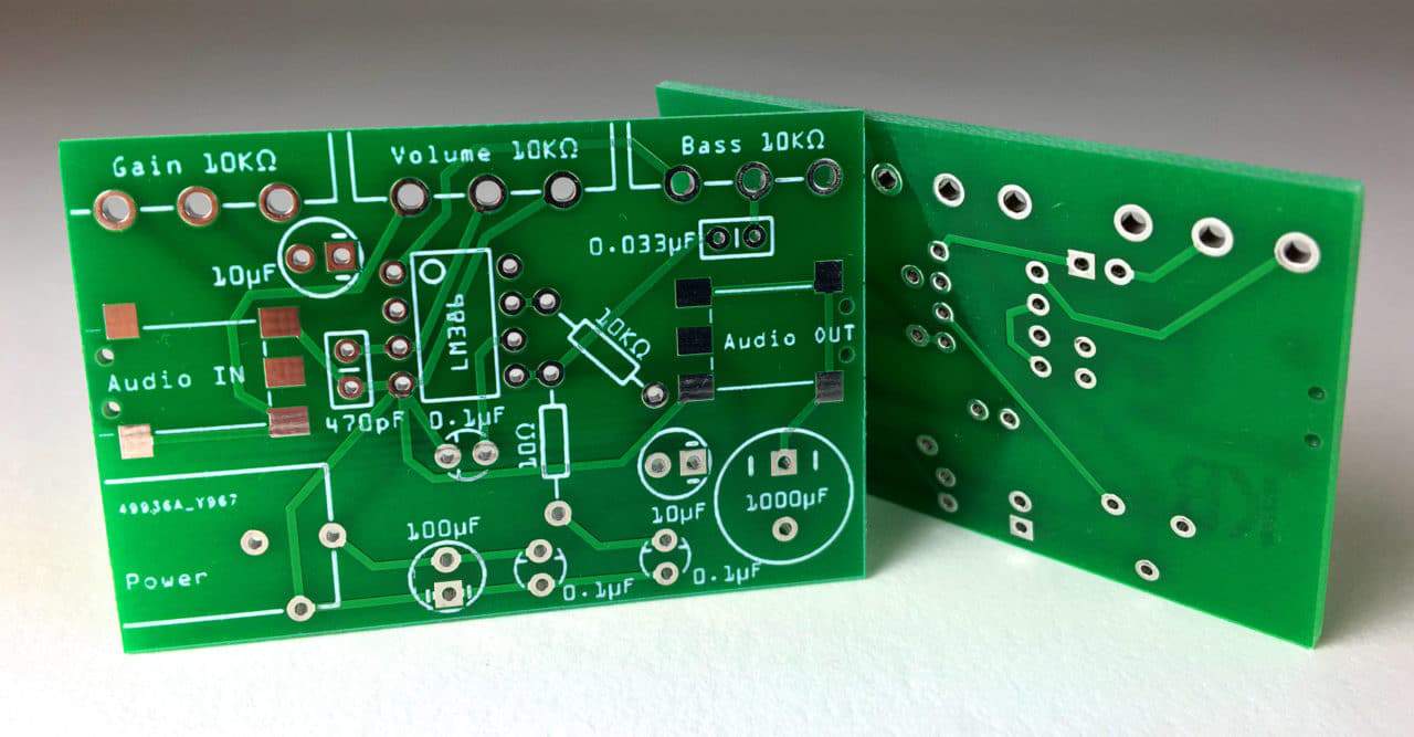
PCBs
PCBs or Printed Circuit Boards are boards with connection pathways printed into the board. These boards are typically used in later stages of prototyping as there isn’t as much flexibility once the board is printed.

Tools
- Soldering Iron and stand

This is the iron used to manipulate the solder onto the board or circuit. A stand is very helpful to hold the iron while it's not in use to avoid touching and burning anything around the iron. They usually come with a sponge or brass wool to clean the tip of the iron.

- Exhaust
Melting the solder often results in the production of fumes, these fumes can be toxic with extended exposure and so, soldering if often done in areas with good ventilation or in the presence of an exhaust system/fan.

- Soldering Mat
Soldering mats are great for protecting surfaces when soldering, it allows you to avoid burning the tables and damaging them. Furthermore, due to the material of most soldering mats they are also anti static and aid in component protection.

- Tweezers and helping hands
Often with smaller components and in the presence of a more complicated circuit, using additional equipment like helping hands or tweezers can help the process. These essentially aid in manipulating the components and keeping them in a specific position.


- Wire Strippers

Wire strippers are used to expose the internal wire and remove the plastic insulation to allow you to create connections between different wires. They are rated for different diameters (or gauges) of wire which is indicated on the tool itself. The American Wire Gauge (AWG) is a standardized way of specifying the size of a wire. Digikey has a wire size conversion calculator for example: https://www.digikey.ca/en/resources/conversion-calculators/conversion-calculator-wire-size

- Flush Cutter
Flush Cutters are great for getting a close and neat cut to the soldered joint!

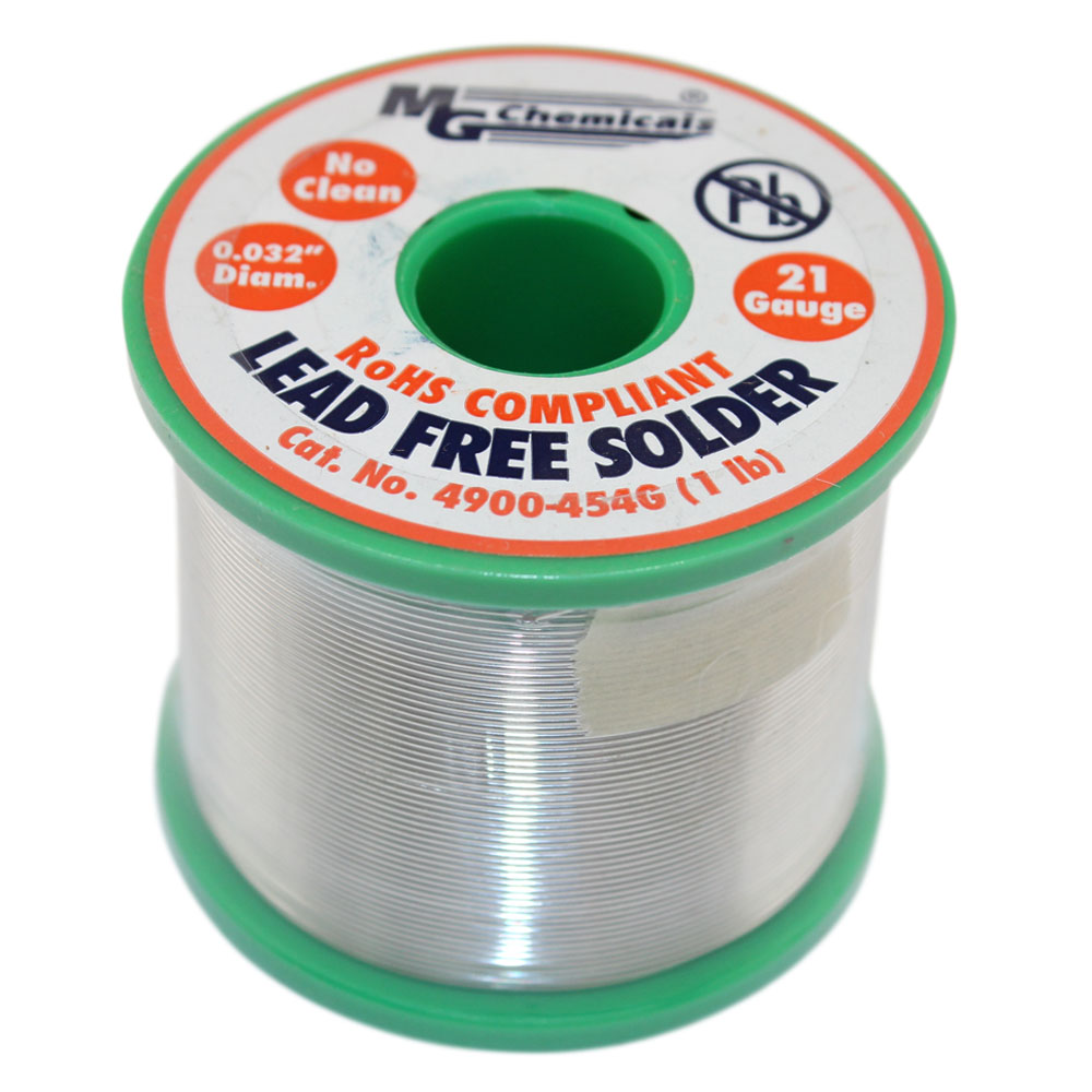
- Solder
The material used to create joints is called solder, this is often sold in rolls of wire, there are different forms of solder that can vary in dimension. Always be sure to use lead free solder as the alternative is toxic. When purchasing solder for circuits, ensure that it isn’t plumbing solder.

- Flux
Flux is a material used to aid in soldering, this chemical removes the oxides on the surfaces of the metals being soldered and allows the solder to flow more uniformly on the joint and components.

- Tip tinner
This chemical aids in cleaning the tip of the soldering iron when it is blackened or very oxidized and helps to solder with far greater ease. This material is great if the iron won’t clean with regular brass wool or sponge.

- Brass Wool and wet sponge
A brass wool can be use to help clean oxidization off of the soldering iron - this aids in adhesion between the soldering iron and the solder. A wet sponge can be used to help clean the iron while soldering. Wet paper towel can also be used.


Tool Maintenance
- Cleaning the iron tip
Either by using a wet sponge or brass wool clean the iron tip regularly in order to remove old solder and oxidization.
- Tin the tip when you are using the iron
Add a small amount of solder to the iron to keep it from oxidizing when you place it in the holder. You can then wipe it off with the sponge/wool before starting to solder.
- Select the correct temperature
- 700F (370C) for through hole components and wires
- 600F (315C) for surface mount components
Higher temperatures can damage the iron and cause it to burn and oxidize faster. It is good practice to use the lowest temperature possible which will still melt the solder. As the tip gets more oxidized a higher temperature will be needed to use it efficiently.
- Do not:
- Do not leave the iron on. Leaving the iron can cause the tip to burn and will ruin in the iron over time.
- Do not file the tip. The tips have a protective coating the will get ruined.
- Don’t touch the mat or any plastics with the iron. A thin plastic film will form on the iron which will inhibit soldering, this includes heat shrink tubing.
How to Solder
Set up
To begin soldering gather all of the equipment and components necessary. And begin by determining which connection needs to be made and how you plan on making it. Next we will set up the Iron and station. Ensure you have a working soldering iron and stand, brass wool/wet sponge, solder, ventilation, and (optional) flux and tip tinner. Turn on the iron and select the appropriate temperature for the iron:
- 700F (370C) for through hole components and wires
- 600F (315C) for surface mount components
Soldering Wires

Soldering two wires is the best way to practice soldering at the very beginning. There are two types of wire, either stranded or solid core. Both have a metal core wrapped in a plastic covering. To see the metal, you need to expose the core by removing the plastic. This can be done using wire strippers or wire cutters. When using wire strippers - place the wire in the slot written to be for the wire gauge you’re using and gently press around the tubing. You want to be sure to avoid cutting through the core of the wire since the goal is to expose the core. Once the perimeter of the covering has been cut through you will then remove it by slipping it off the core as seen below.
How does the wire stripper work?
The wire stripper works by having blades that are circular in shape and of different diameters that correspond to different wire gauges. The wire cutter is designed to cut through the sheath on a wire whilst not cutting through its core.
- Grab a few wires, strip 1 cm off each end.
- Twist the two wires together with pliers or your fingers.
- Hold the soldering iron like a pen. Heat the two wires for 1-2 seconds and then flow solder on the connection. The goal is to heat the connection not the solder. Once you see the solder flow evenly throughout the connection, remove the solder and soldering iron.
- Long exposure of the iron to the PCB and other electronic components will lead to them burning so make sure you don't leave the iron there for too long.
- Allow the connection to cool, this usually takes 20-30 seconds. During this time, avoid moving the wires.
Soldering THT
- Place the lead (metal stick coming from component) or wire through the hole in the protoboard or PCB. Bend the leads slightly to the outside so the component doesn't fall through.
- Holding the soldering iron like a pen, heat the copper pad and lead with the soldering iron until the solder begins to flow and forms a strong connection. Remove solder, and then the soldering iron. This process should take only a few seconds.
- Long exposure of the iron to the PCB and other electronic components will lead to them burning so make sure you don't leave the iron there for too long.
- Allow for the connection to cool.
- Snip off the excess lead as close as possible to the board with wire cutters or flush cutters.
When soldering be sure that you don't use too much or too little solder - as seen below, ideally the joint should have a cone shape to it.

Soldering Considerations
Polarity
When soldering different components be sure to consider their polarity! Often times certain components will only work when connected a certain way, and example of such a component is an LED. LEDs have a positive and negative end and the component will only work when connected in a certain manner.

Heat Sensitivity
Due to various reasons such as material or size, certain components are only able to handle certain levels of heat when being soldered. If exposed to too much heat for too long, they are likely to burn out and become unusable.
Static Electricity
Certain components are incredibly sensitive to static electricity and thus require specific equipment when handling them. There are 4 types of ESD equipment used to aid in grounding you to avoid damaging the equipment.
There are gloves, mats, a wrist strap, and a bag, learn more about ESD Equipment here
