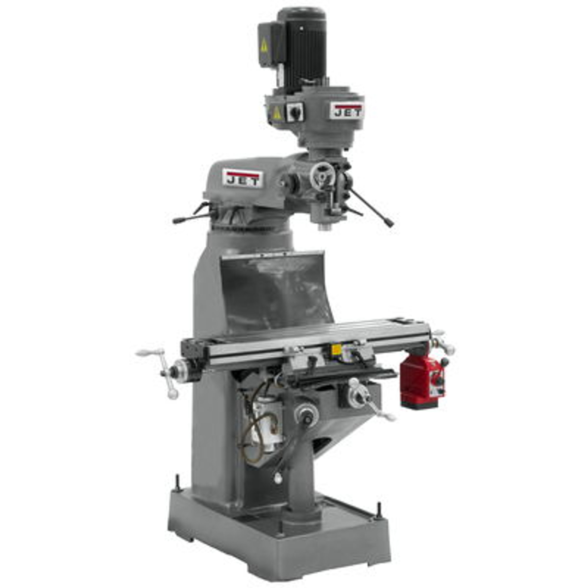
Mill
Intro

The milling machine—commonly referred to as “the mill”—is one of the most versatile and widely used tools in any machine shop. Unlike a drill press, which cuts only in the vertical axis, a mill allows for precise movement in the X (left/right), Y (forward/back), and Z (up/down) directions, enabling complex and accurate machining operations on a wide range of materials.
Mills remove material using a rotating cutting tool held in a spindle, allowing operators to shape metal and plastic parts with high precision. In our shop, we primarily use vertical knee mills equipped with digital readouts (DROs), allowing for repeatable and accurate setups.
Whether you're facing a part flat, drilling a precise hole, cutting a slot, or using a form tool to create complex geometry, the mill is essential for prototype work, part modification, and precision fabrication.
This guide will walk through how mills work, the operations they can perform, how to choose the right tools, proper setup techniques, and what to watch for during machining.
How the Mill Works
A milling machine operates by rotating a cutting tool (such as an endmill) while moving a workpiece against it. Material is removed through the shearing action of the rotating cutter, allowing for precise shaping of metal, plastic, or other materials.
Key Components
- Spindle
- The spindle holds and rotates the cutting tool. It's powered by a motor and can run at various speeds, depending on the material and operation.
- Table
- The flat surface that holds the workpiece. It can move in the X-axis (left/right) and Y-axis (in/out). Movement is controlled by handwheels or power feeds.
- Knee & Column
- The knee supports the table and moves vertically along the column, giving the Z-axis (up/down) motion.
- Quill
- Found on most vertical mills, the quill allows for vertical movement of the spindle—useful for drilling or plunging into material.
- Digital Readout (DRO)
- A DRO displays the precise position of the table along each axis. It greatly improves accuracy and efficiency, especially for repetitive work.
The X-axis power feed controller (red box) with a control lever to change feed direction.
- A DRO displays the precise position of the table along each axis. It greatly improves accuracy and efficiency, especially for repetitive work.

Modes of Movement
- Manual - Most shop mills are manual, meaning the operator turns handwheels to control table motion and spindle feed.
- Power Feed - Our Brunsfield mills have powered X-axis feeds. These are useful for consistent finish during long cuts like face milling.
- Locking Mechanisms - Axis locks are used to prevent unwanted movement. It's good practice to lock any axis not in use during a cut.
How Cutting Happens
- The cutter spins at a selected RPM, chosen based on material, tool diameter, and cutter type.
- The workpiece is moved against the spinning cutter, removing material layer by layer.
- Different cutters and operations (face milling, slotting, drilling, etc.) change how the cut engages the workpiece.
- Chip formation and cutting load depend on feed rate, depth of cut, and cutter geometry.
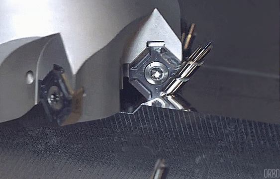
Each pass of the tool cuts a chip of metal from the workpiece.

Feed & Speed
- Spindle Speed (RPM) affects how fast the cutter rotates. Too fast and you'll burn the cutter; too slow and it may chatter or rub instead of cut.
- Feed Rate is how fast the workpiece moves into the cutter. It must be matched to the material and tool geometry to ensure clean cutting and tool life.
- While machining, always apply coolant to mitigate heat production, minimize tool wear, and improve surface finish. See the coolant page for more info.
Quick Start Guide
Mill Controls


The following images show the main controls on the milling machine, their functions are listed below:
- On/Off switch - Activates the motor on the mill.
- Speed Adjustment dial - Changes the rpm of the spindle while the mill is running.
- High/Low Gear Handle - Changes the running speed gear of the mill.
- Quill Pilot Feed Lever - Lowers & raises the spindle, used for drilling.
- Quill lock - Locks the spindle in the current position.
- Quill power feed - Used for fine adjustments of the spindle height.
- DRO - Displays the current X and Y axis position. Can be set to metric or imperial units.
- Vise - The vise is bolted to the mill table and holds the workpiece during operation.
- Y/X axis feed wheels - adjust the X & Y position of the table via clockwise or counterclockwise rotation.
- Z-axis knee lever - Adjusts the height of the table. Used to set proper working height for an operations. Changing this does not change the Z-axis DRO reading.
Primary operations on the mill are face milling, side milling, and drilling.
See a full run down of all the milling operations:
Indicating
Before making any cuts, it's critical to establish a working zero—a reference point from which all other dimensions are measured. On a milling machine with a digital readout (DRO), this is usually done by locating the edge of your part, or the vise, with an edge finder and then setting the DRO coordinates accordingly.

What is an Edge Finder?
An edge finder is a precision tool used to locate the exact edge of a workpiece. When used properly, it can help you zero your X and Y axes within a few thousandths of an inch. Most edge finders have a tip that is 0.200" in diameter, meaning it has a radius of 0.100". The tip of the tool is attached with a magnet, allowing it to move when it contacts your piece while spinning.

Step-by-Step Process
- Mount the Edge Finder - Insert the edge finder into a collet (preferably not a drill cuck for accuracy reasons) and snug it up in the spindle. Make sure your mill is set to a low RPM—between 800 and 1200 is ideal.
- Knock the Edge Finder off center - With your finger, push the tip of the edge finder so that it sits out of line with the rest of the tool
- Spin the Edge Finder - Start the mill and bring the spinning tip near the part edge. As you feed the part slowly toward the tool, you'll notice the tip wobbles eccentrically.
- Touch Off the Edge - As you get closer, the tip will suddenly "kick" and run true just before it jumps off. That moment of alignment—right before the jump—is your edge contact point.
- Read the DRO - At this point, your tool center is still offset from the actual part edge by half the diameter of the edge finder (typically 0.100").
- Set the Zero - Subtract the radius from the current DRO reading. For example, if the edge finder touches off and your DRO reads 0.000", your actual part edge is at -0.100".
- Set your DRO to -0.100", then jog the axis until it reads 0.000", and set this as your zero.
- Repeat the same process for both X and Y edges if you're zeroing from a corner. Once both axes are zeroed, jog to any known feature on the part and verify against your print or CAD model.
`
Pro Tips
- Always approach from the same direction you plan to cut—this compensates for backlash.
- Use parallels if your part isn’t sitting directly on the vise bed, and indicate the top surface as your Z zero if needed.
- Don’t forget to lock the axis not in use while touching off for added rigidity.
- If your edge finder tip is chipped or the wobble doesn't go away smoothly, replace it—it’s no longer accurate.

Endmills
Endmills are the workhorses of the milling machine. These rotary cutters remove material using their flutes, and they come in a wide variety of materials, flute counts, and geometries. Selecting the right endmill affects surface finish, tool life, and cutting efficiency.
HSS vs. Carbide Endmills
Endmills are commonly made from either high-speed steel (HSS) or carbide. HSS tools are inexpensive, relatively tough, and ideal for general-purpose milling, especially at lower spindle speeds. They’re forgiving if the setup isn’t perfect, making them a good choice for students or roughing operations. Carbide endmills, on the other hand, are harder and more wear-resistant, making them ideal for harder materials and high-speed milling. Carbide also provides better finishes and lasts longer, but it's more brittle—meaning it can chip or snap if misused or dropped. In most teaching shops, you'll use both: HSS for roughing or learning, and carbide when you need precision, high feed rates, or are cutting tougher materials like steel or aluminum alloys.

2-Flute vs. 4-Flute Endmills
Flute count has a major impact on how an endmill performs. 2-flute endmills have wider spaces (gullets) between the cutting edges, which means they can clear chips more easily. This makes them ideal for machining softer materials like aluminum, where chip clogging is a concern, and also for slotting operations where chips have nowhere to escape. 4-flute endmills have more cutting edges in contact with the material at once, leading to faster metal removal and smoother surface finishes, especially in harder materials like steel. However, they don’t clear chips as easily and are less ideal for deep slots unless you adjust feed rates and use coolant or air blast. As a general rule: use 2-flutes for aluminum and slotting, and 4-flutes for steel and side milling.
Reground vs. New Endmills
In a Brunsfield, you’ll likely come across reground endmills—cutters that have been resharpened to extend their life. Reground tools are great for roughing passes or when surface finish isn’t critical. They’re cheaper and environmentally friendly, but they may be slightly shorter, have worn coatings, or exhibit minor runout. For high-precision features, smoother finishes, or very tight tolerances, it’s best to use new endmills, which have factory-ground edges and full cutting length.

Ball Nose Endmills
A ball nose endmill has a rounded tip rather than a flat one. This geometry is essential for contouring and 3D profiling, such as in molds or sculpted parts. They’re used when you want to avoid sharp inside corners or need to produce a smooth surface on a curved feature. However, they leave a scalloped finish unless stepovers are very fine, and they’re less rigid at the tip, so they’re not ideal for deep cuts. Use them for finishing passes on 3D surfaces or for parts that require smooth transitions.
Workpiece Holding and Setup
Securing both the tool and the workpiece properly is essential to accurate, safe, and efficient milling. A loose setup will lead to poor finishes, chatter, and dangerous tool breakage. Here’s a breakdown of the most common equipment used in the shop for setup and holding.
Tool Holding: Collets vs. Drill Chucks

R8 Collets
R8 collets are the standard tool holders in most manual milling machines. They grip the shank of the cutting tool with good concentricity (low runout), making them ideal for endmills, edge finders, and center drills. Each collet size corresponds to a specific tool diameter—so you’ll need to match the collet to your tool shank.
- Pros: Accurate, secure, low runout
- Cons: Requires swapping for different shank sizes
Drill Chucks
Used for holding drill bits or reamers, drill chucks grip the tool with jaws tightened by a chuck key. They're only suitable for axial operations like drilling. Never use a drill chuck for side milling—cutting forces can pull the tool out or cause slippage.
- Pros: Quick tool changes, versatile for drilling
- Cons: Not secure for milling—can slip or wobble
Workpiece holding Tools
Milling Vise
The milling vise is the go-to workpiece holding tool in most shops. It clamps your part securely and aligns it square to the machine’s table. The vice uses a removable handle to open and close the jaws. The handle is stored hanging from the table when not in use.
It’s usually bolted down with T-slot hardware. Always check that your part is sitting flat and square in the vise. Indicating the vise to check if it's sitting square can be done using a Dial Indicator. See the "Maintenance" section.
Pro Tip: Use a mallet or dead-blow hammer to "seat" your part after snugging the vise but before final tightening.


Slot Clamping Kit (T-Slot Clamps)
Used for clamping irregular or oversized parts directly to the mill table. The kit includes step blocks, strap clamps, nuts, bolts, and T-nuts that fit into the machine’s T-slots.
- Good For: Holding plates, large parts, or when the vise won’t work
- Caution: Ensure clamps are level and square—uneven clamping can distort the part
Setup Aids and Accessories
Parallels
Parallels are precision-ground bars used to elevate a part inside the vise. They ensure that the part sits flat and level, and allow tool clearance below the part (e.g., for through-holes or full-depth slots). Choose a pair that keeps your part slightly above the vise jaws.
- Watch out for: Chips under the parallels—this will throw off your Z zero!


123 Blocks
Precision-ground steel blocks sized 1" x 2" x 3". They’re used as reference spacers, squaring aids, or even mini angle plates. Can be clamped together or to the table to help with odd setups.
- Common Uses: Squaring a part in the vise, setting Z-depths, or elevating parts outside the vise
Collet Blocks
Collet blocks hold round or hex stock using a standard collet, allowing it to be clamped securely in the mill vise. They’re useful when machining multiple flats on round material or performing indexed operations.
- Types: Square blocks (for 4 sides), hex blocks (for 6 sides)


Angle Plates
Used to hold parts vertically or at 90° angles to the table. Precision-ground and drilled with mounting holes. Often used in combination with clamps or vises to machine edges or ends of tall parts.
- Tip: Check squareness with an indicator before cutting

Rotary Table (Turntable)
This allows controlled rotation of the part around a vertical axis. It's useful for machining circular patterns, bolt hole arrays, or radii. The table can be indexed manually in degrees or divided using index plates.
- Common Uses: Cutting arcs, drilling hole circles, machining gears
- Note: Always lock the axis you’re not using—these setups require careful planning
General Setup Tips
- Always clean mating surfaces (table, vise bottom, parallels) to prevent misalignment. Use brushes instead of your hands as chips can be sharp.
- Double-check part squareness before cutting—tap it down or into the jaws using a soft mallet
- Use the smallest clamp/holder that safely gets the job done—fewer things in the way means fewer chances for accidents
- Lock unused table axes when making a cut for better rigidity
- Take time with setup—the more precise your setup, the less trouble you’ll have during machining
Monitoring the cut
Sound: What You're Hearing
Smooth, consistent hum - Ideal. Indicates proper feed/speed and good tool engagement.
Light squealing or whining - Usually a sign of rubbing instead of cutting—possibly from dull tools, too low feed, or incorrect RPM.
Chatter or rhythmic vibrations - A telltale sign of tool deflection, loose setups, or excessive stick-out. You'll hear a high-pitched “buzz” or “hammering” noise that worsens as the cut continues. Stop and address it.
Clunking or knocking - Indicates serious instability—tool looseness, bad bearings, or a poorly clamped part. Stop immediately and inspect.
Screaming or howling - Often a sign of way too high spindle speed or aggressive cutting with a brittle cutter (e.g., carbide). Check RPM and tool sharpness.
Chip Shape and Color

Chips are your best real-time indicator of whether your cutter is performing well.
- Consistent, curled chips - Ideal. Suggests good chip evacuation and balanced feed/speed.
- Tiny dust-like chips - Feed too low or tool rubbing instead of cutting.
- Blue or black chips - Overheating—too much speed or not enough coolant/air. May damage the tool or workpiece.
- Long, stringy chips (esp. in aluminum) - Feed might be too low. Also risk of chip wrapping around the cutter—clear frequently.
- Powdery chips - Could indicate abrasive wear on the tool or surface hardening on the material. Dull tools or the wrong cutter for the job.

Surface Finish and Vibration
- Smooth finish with uniform texture - You’re doing great! Keep everything the same.
- Scalloped or ridged finish - Usually from too fast feed or tool chatter. May also mean the spindle is loose or the part is vibrating.
- Chatter marks (evenly spaced ripples) - Tool deflection or mechanical looseness. Check clamping, tool length, and feed speed.
- Random gouges or digs - Tool might be loose or broken. Shut down and inspect everything.
Vibration and Machine Feedback
- Stable, solid feel - Good setup. Axes are locked and the machine is working with you.
- Mild vibration through the handwheels or table - Not ideal—could be cutting too aggressively, or the setup might be slightly loose.
- Visible shaking or movement of the part or tool - Serious issue. Stop immediately. Recheck clamping, tool stick-out, and speed/feed.
- Tool deflection - Especially in longer or smaller-diameter tools, the cutter may bend under load, causing undersize cuts or chatter. Use a more rigid setup or adjust depth of cut.
Operator Intuition: Know the Signs
- “This sounds smooth and stable.” Keep going.
- “Something doesn’t feel right, but I can’t see it yet.” Trust that instinct—pause and inspect.
- “It’s cutting fine, but my finish looks bad.” Try lowering the speed or increasing feed slightly (or both).
- “The chips are changing color or shape.” Reassess your feed/speed and chip evacuation.
Safety Considerations
The milling machine is one of the most powerful and versatile tools in the shop—but with that comes responsibility. Rotating tools, sharp cutters, and heavy parts can cause serious injuries if proper safety practices are not followed. Whether you're new to the machine or an experienced operator, safety always comes first.
PPE
- Safety Glasses: Always required. Protects against flying chips or broken tools.
- Hearing Protection: Recommended, especially during long cuts or when using high RPMs.
- Non-Synthetic Clothing: Avoid synthetics that can melt or ignite. Cotton or natural fiber clothing is best.
- Closed-Toe Shoes: Steel-toes are ideal. Never wear sandals or open footwear.
- Gloves: Never wear gloves near rotating tools. Gloves can catch and pull your hand into the machine.
- Hair and Jewelry: Tie back long hair and remove rings, watches, and dangling jewelry.
General Safety Rules
- Never leave the machine running unattended. Always be present and alert when the spindle is on.
- Keep the area clean and free of clutter. Chips, tools, and loose rags create tripping and entanglement hazards.
- Use a brush or chip hook to remove chips. Never use your hands, even with gloves.
- Always check for tool tightness. Ensure the tool is properly seated and tightened in the collet before starting the spindle.
- Double-check your setup. Loose vises, parallels, or improperly clamped workpieces are a major hazard.
- Know where the emergency stop is. Be ready to use it.
Machine-Specific Hazards
- Rotating Spindle and Tooling: Never reach near the cutter when the machine is running. Even a spinning tool that’s "not cutting" is dangerous.
- Kickback and Tool Pullout: Improper tool holding (like using a drill chuck for an endmill) can result in tools being thrown.
- Flying Chips and Debris: Chips can come off hot and fast—use chip shields if available.
- Unexpected Movement: If power feed or DRO is engaged improperly, the table can move quickly—keep hands clear.
Common Safety Mistakes to Avoid
- Wearing gloves or long sleeves while operating the machine
- Using a drill chuck to hold an endmill
- Leaving the key in the drill chuck
- Reaching over a spinning tool to brush off chips
- Using damaged or dull tooling
- Forgetting to lock the axes before a cut
- Starting the spindle before securing the part
- Not checking spindle direction—some tools will unscrew themselves or cut incorrectly if running backward.
Maintenance
Before performing any accurate milling operation, it’s important to make sure your spindle is perpendicular to the table (tramming) and your vise is aligned parallel to the machine axes (indicating). Without these checks, your cuts can end up angled, off-center, or out of spec—even if everything else seems right.
Even if the head is trammed, your cuts won’t be square unless the vise jaws are parallel to the X-axis travel. This process is called indicating the vise. This process involved placing a parallel into the vice, and running a dial indicator along its length while taking not of the change in position at each end. If there is significant deviation along the parallel, it tells you that the vice is not sitting square to the table.
Tramming refers to adjusting the mill head so that the spindle is perfectly perpendicular to the table. On manual mills with tilting heads (like Bridgeport-style mills), this is a common maintenance and setup task—especially if the head has been rotated for a previous job.
This process involves comparing the measurement of each dial indicator on the tramming tool at various points on the mill table. This can tell you if the head of the mill needs to be clocked side to side or front & back.