Facing is the process of creating a smooth, flat surface on the end of a cylindrical workpiece. It is often the first operation performed when preparing stock.
Hazards: Sharp surfaces, hot parts, pinch points, high loads
Mistakes: Bad DOC/feed, no coolant, hitting chuck, tool too high/low, excessive stickout
Mitigation: Use chip chart, check feeds/speeds, always use coolant on steel, document limits
Tips: Move at constant speed, support stickout >3x dia
1. Secure the Workpiece
Insert the stock material into the chuck and tighten all three jaws evenly.
Ensure at least 2–3 jaw widths are gripping the material.
Support long overhangs with a tailstock or follow rest (stickout should not exceed 3× diameter without support).
2. Set Up the Tool
Mount the facing tool in the tool post with the cutting edge at center height.
Square the tool perpendicular to the face of the workpiece
Ensure the tool overhang is minimized and tightened securely in the holder.
3. Check Feeds, Speeds
Refer to the feeds and speeds chart for the material type.
Use coolant or cutting fluid for steel or tough materials.
4. Begin Facing
Lower the chuck guard.
Start the spindle at the proper speed.
Use the z axis to touch off on your part and 0 the DRO
Set your Depth of Cut (DOC) in accordance with the feeds and speeds sheet
Feed steadily toward the centerline.
Avoid stopping directly at the center (this causes poor surface finish due to tool geometry).
5. Monitor the Cut
Watch for chip formation — chips should be consistent.
Listen for chatter or tool rubbing and adjust feed or speed as needed.
Use coolant to manage heat and improve finish.
6. Finishing the Face
Make a final light pass to clean up the surface.
Retract the tool safely before stopping the lathe.
7. Clean Up
Turn off the spindle and wait for it to stop completely.
Use a brush to clean the area (never your hands).
Deburr the faced surface if needed.
Turning (Class 2)
Turning is the process of removing material from the outer diameter of a rotating workpiece using a stationary cutting tool. It is commonly used to reduce diameter, create smooth cylindrical surfaces, and produce features like shoulders or tapers.
Hazards: Sharp surfaces, hot parts, pinch points, high loads
Mistakes: Bad DOC/feed, no coolant, hitting chuck, tool too high/low, excessive stickout
Mitigation: Use chip chart, check feeds/speeds, always use coolant on steel, document limits
Tips: Move at constant speed, support stickout >3x dia
1. Secure the Workpiece
Insert your material into the chuck and tighten all jaws evenly.
Ensure the workpiece is concentric and at least 2–3 jaw widths are clamped.
If stickout exceeds 3× diameter, support the end with the tailstock or follow rest.
2. Install and Align the Tool
Mount a right-hand turning tool in the tool post.
Ensure the cutting edge is at center height.
Align the tool parallel to the workpiece and minimize tool overhang.
Tighten the tool securely in the post.
3. Set Feeds, Speeds
Consult the feeds and speeds chart for your material.
Use coolant for steel or other hard metals.
Set feedrate according to desired finish and rigidity.
4. Begin the Turning Operation
Close the guard
Stand clear of rotating parts and start the spindle at the appropriate RPM.
Use the cross-slide to touch off on the surface of the workpiece and 0 the DRO
Steadily move the Z axis towards the chuck
5. Monitor the Cut
Chips should be consistent and curl away cleanly.
Watch for signs of chatter, rubbing, or poor chip formation.
Use cutting fluid if needed and adjust feed or speed if surface quality degrades.
6. Take Additional Passes
Retract the tool at the end of each pass using the cross-slide.
Adjust DOC and make subsequent passes until the final diameter is reached.
For finishing, take light passes with slower feed.
7. Measure and Inspect
Stop the machine and use calipers or micrometer to measure the turned diameter.
Deburr sharp edges and verify concentricity or tolerance if required.
8. Shut Down and Clean
Turn off the lathe and wait until the spindle stops fully. (Use the foot break)
Remove chips using a brush or chip hook.
Clean the area and return tools to their proper place.
Parting
Parting (Class 5)
Parting is the process of cutting off a section of a workpiece using a thin tool that moves perpendicularly into the rotating material. It is one of the most sensitive and potentially hazardous lathe operations.
- Hazards: Pinch points, high loads, rotating parts
- Mistakes: Tool not centered, inadequate support, high speed
- Mitigation: Square tool post, go very slow, minimal pressure
Ensure the workpiece is tightly clamped in the chuck with sufficient grip (at least 2–3 jaw widths).
Use the tailstock for support if the part is long or overhangs significantly.
Always perform parting close to the chuck to reduce tool deflection and chatter.
2. Set Up the Parting Tool
Mount the parting blade vertically in a rigid tool holder.
Confirm the cutting edge is aligned exactly at center height.
Ensure the blade is square to the workpiece and tightly secured.
Keep overhang of the blade as short as possible to reduce flex.
3. Set Feeds, Speeds, and Coolant
Refer to the lathe speed chart — parting requires lower RPM than normal turning.
Always use coolant or cutting fluid (especially for steel).
Power feed may be used, but manual feed is recommended for better control.
Feed should be steady and moderate, not forced.
4. Start the Cut
Stand to the side, clear of rotating parts, and start the spindle at the correct speed.
Engage the cross-slide to advance the tool into the rotating workpiece slowly and steadily.
Watch and feel for signs of chatter or resistance — stop and reassess if needed.
5. Monitor the Operation
Use steady feed pressure — do not stop and restart mid-cut unless necessary.
Keep the groove flooded with coolant to clear chips and reduce heat.
Watch your chip formation — long, continuous chips are a warning sign. Chips should break and clear cleanly.
6. Complete the Cut
Just before the part separates, hold it gently with your hand or catch with a cloth to avoid it flying off (if safe to do so).
Stop the feed just as the part is about to fall off and then manually finish the last bit slowly.
For large or heavy parts, use the tailstock or a stop to catch the part safely.
7. Post-Cut Actions
Stop the lathe completely.
Remove the parted-off section and deburr the cut face.
Inspect the tool for wear or chipping before next use.
8. Clean Up
Turn off the machine.
Use a brush to clean away chips (never your hands).
Return the parting tool and any accessories to their proper location.
Drilling (Class 2)
Drilling on the lathe involves feeding a stationary drill bit into a rotating workpiece using the tailstock. This ensures perfectly concentric holes and is commonly used before boring, reaming, or threading.
Drilling
- Hazards: Chip binding, sharp tools, rotating bit
- Mistakes: No center drill, bad chip evacuation, wrong speed
- Mitigation: Use pecking, coolant, proper clamping
- Tips: Ensure chip removal, check flutes, use drill charts
1. Face the Workpiece
Always face the end of the part before drilling.
Prevents the drill bit from wandering and ensures a perpendicular entry.
2. Install the Drill Bit
Select the appropriate center drill and twist drill.
Insert into the tailstock drill chuck and tighten securely with the chuck key.
For larger holes, step up through multiple drill sizes to reduce tool strain.
3. Align and Zero
Manually advance the quill until the drill tip just contacts the workpiece face.
Zero the Z-axis DRO or note the tailstock handwheel position for tracking depth.
4. Set Speed and Coolant
Use the formula RPM = (3 × Cutting Speed) ÷ Diameter.
Refer to the feeds and speeds chart on the lathe backboard.
Always use cutting fluid for steel or deep holes.
5. Center Drill First
Start the lathe at a slow speed.
Use the center drill to make a shallow, conical starter hole.
Retract, stop the machine, and switch to your twist drill.
6. Drill the Hole
Restart the lathe and gently feed the drill into the part using the tailstock handwheel.
Peck drill: drill a short distance, retract to clear chips, then repeat.
Continue until the desired depth is reached.
7. Finish and Inspect
Slow the feed as you approach the final depth.
Retract the bit carefully to avoid damaging the hole.
Measure depth and diameter as needed.
8. Clean Up
Remove and return the drill bits to the proper location.
Wipe down the tailstock taper and chuck.
Clear chips from the machine bed and surrounding area using a brush or rag.
Boring (Class 3)
Boring is the process of enlarging and finishing an existing hole using a single-point cutting tool. It is used for precision internal diameters, improved surface finish, or concentricity relative to the lathe spindle.
Boring
- Hazards: pinch points
- Mistakes: Long boring bar, wrong DOC/feed
- Mitigation: Use wider/shorter boring bars, small DOC
- Tips: Avoid chatter, don’t force the tool, bore only if hole clearance is sufficient
1. Prerequisite – Start with a Drilled Hole
Boring tools cannot start a hole — use a center drill and twist drill first.
The pilot hole must be at least slightly larger than the boring bar’s tip.
2. Select the Boring Tool
Choose a short, rigid boring bar for shallow holes.
Use a larger diameter or longer bar for deeper bores — avoid deflection.
Tool cutting edge must be at center height and properly oriented.
Mount in a rigid tool holder with minimal overhang.
3. Set Up the Workpiece
Face the part if necessary and drill a pilot hole.
Clamp securely in the chuck with minimal stickout.
For deep bores, consider tailstock support for the opposite end of the part.
4. Set RPM and Coolant
Use lower spindle speeds than for turning (reduce chatter).
Refer to feeds and speeds chart on the backboard.
Use cutting fluid or coolant, especially for steel or deep holes.
5. Begin Boring
Start the lathe and bring the boring tool into the pilot hole using the cross-slide.
Feed longitudinally (Z-axis) with the carriage, slowly and steadily.
For deeper cuts, consider pecking to help clear chips.
6. Monitor for Chatter
Watch and listen for vibration or noise — reduce DOC or feed if needed.
Minimize overhang and use more rigid bars for long bores.
Never force the tool — boring requires smooth, light pressure.
7. Measure and Adjust
Stop the lathe and measure the bore diameter frequently using telescoping gauges, bore micrometers, or internal calipers.
Take light finishing passes (0.005"–0.020") for final dimension.
Only bore holes that are larger than the minimum bar clearance.
8. Clean Up
Retract the boring bar fully before stopping the spindle.
Clear out all chips from the bore with a brush or air (if safe).
Clean the boring bar and return it to its drawer or holder.
Knurling (Class 3)
Knurling is the process of impressing a textured pattern onto the surface of a cylindrical workpiece using hardened knurling wheels. It is often used to create grippable surfaces on handles or knobs. - Hazards: Pinch points, hot surfaces
Knurling
- Mistakes: Poor alignment or pressure
- Mitigation: Align tool center, feed slowly, use coolant
- Tips: Use slow RPM, keep hands clear
1. Choose Knurling Method
Bump knurling : presses the knurling wheels into the part using feed pressure.
Suitable for lighter machines or softer materials.
Pinch knurling (dual-wheel): two wheels squeeze the part from opposite sides.
Preferred for steel, rigid setups, and better alignment.
Puts less stress on the lathe spindle.
2. Select and Install Knurling Tool
Choose the appropriate knurl pattern
Mount the knurling tool square to the workpiece in the tool post.
Set tool height so the wheels are at centerline of the part.
For pinch knurling, ensure both wheels align evenly on either side.
3. Set Up the Workpiece
Clamp the part securely in the chuck.
Minimize stickout to prevent deflection under pressure.
Knurling should be done on flat, clean surfaces with no scale or rust.
4. Set RPM and Coolant
Use low spindle speed: ~100–200 RPM is typical.
Apply cutting fluid or coolant generously to prevent tearing and improve finish.
5. Begin the Knurling Pass
Bump method:
Start the spindle. (Often with spindle jog button)
Feed the wheels directly into the surface with firm, steady pressure.
Let the pattern fully form before feeding along the length.
Pinch method:
Bring both wheels into contact at center height and apply even pressure.
Slowly traverse the carriage to cover the knurling area.
No depth feed is needed—pressure between wheels does the work.
6. Inspect and Repeat if Needed
If pattern is partial or skipping:
Increase pressure slightly, slow the feed, or re-align the tool.
Never dwell in one spot—keep feeding slowly to avoid double-tracking.
7. Clean Up
Retract the tool and stop the machine.
Deburr the ends of the knurled area with a file if needed.
Wipe down the tool and machine area; remove chips and excess fluid.
Threading (Class 3)
Threading on the King KC-1440ML lathe involves using the leadscrew and half-nut lever to synchronize the tool movement with spindle rotation, allowing you to cut precise threads on a rotating workpiece.
Threading
- Hazards: Tool breakage, sharp edges
- Mistakes: Wrong pitch, incorrect dial use
- Mitigation: Scratch pass, check pitch, slow RPM
- Tips: Use cutting fluid, ask staff if unsure
1. Face and Center the Part
Always face the part and use a center drill if needed to prep for tailstock support.
Ensure you have enough clearance behind the threading area or add a groove relief.
Imperial Thread Pitch Chart
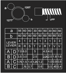
2. Select Thread Pitch and Setup Gearbox
Use the threading chart on the lathe’s front panel to set the gearbox levers.
Confirm whether you're cutting imperial or metric threads — these require different gear positions.
For metric threads, do not disengage the half-nut mid-pass; use the carriage handwheel to return.
3. Mount and Align the Threading Tool
Use a properly ground threading tool (60° for standard threads).
Set tool exactly on center height using a height gauge or live center.
Metric Thread Pitch ChartUse a thread gauge or part print to confirm pitch angle and dimensions.
Square the tool to the part using a small machinist's square or threading alignment tool.
4. Set RPM and Dial
Run the lathe at low speed (typically 60–100 RPM).
Engage the threading dial for imperial threads.
For imperial threads: only engage the half-nut at marked numbers on the dial.
For metric threads: leave the half-nut engaged continuously and reverse the spindle between passes.
5. Perform a Scratch Pass
With the compound set at 29° (for single-point imperial threading), take a light scratch pass.
Stop the lathe, measure the thread pitch with a pitch gauge, and confirm correctness.
6. Cut Threads
Advance the compound slightly for each pass (~0.002"–0.005").
Engage the half-nut at the correct threading dial mark (imperial only).
Retract the cross-slide after each pass, reverse the carriage, then reset cross-slide to zero.
Repeat until thread depth is achieved (check against tap, nut, or thread gauge).
7. Check Fit and Finish
Use a thread pitch gauge, mating part, or thread ring gauge to verify the thread.
For internal threads, check using a matching bolt or plug gauge.
Use cutting oil throughout to reduce wear and improve surface finish.
8. Clean Up
Disengage the half-nut and turn off the machine.
Deburr the thread start and end.
Clean the area thoroughly — threading produces long, stringy chips.
Reaming (Class 3)
Reaming is used to finish and precisely size an existing hole. It does not remove large amounts of material—instead, it refines the surface finish and brings the hole to a tight tolerance.
Reaming
- Hazards: Tool binding, heat, sharp edges
- Mistakes: Hole too small, feed too fast
- Mitigation: Undersize drill by 0.005"-0.002" , slow feed
- Tips: Never ream oversize, reamers are finishing tools
1. Drill the Hole First
Use a twist drill to create a hole approximately 0.005"–0.020" (0.2–0.5 mm) under the final desired size.
The pilot hole must be straight and clean, preferably with a center-drilled start.
2. Select and Install the Reamer
Choose the correct machine reamer (not a hand reamer).
Insert it into the tailstock drill chuck and tighten securely with the chuck key.
Ensure the reamer is clean and undamaged—do not use dull or chipped reamers.
3. Set Speed and Lubrication
Set the lathe to a low spindle speed: approximately half the RPM used for drilling the same size.
Use plenty of cutting fluid or coolant, especially for steel or deep holes.
Refer to the feeds and speeds chart on the backboard for guidance.
4. Ream the Hole
Start the lathe and feed the reamer in slowly and steadily using the tailstock quill.
Do not reverse the spindle while the reamer is engaged in the part.
Do not peck—reaming is a continuous operation.
Do not force the reamer — let it cut under light pressure.
5. Retract and Inspect
Once depth is reached, stop the spindle and manually retract the reamer slowly to avoid marring the surface.
Inspect the bore using a plug gauge, bore micrometer, or caliper to confirm the final size.
Deburr the hole if needed.
6. Clean Up
Remove the reamer and clean it carefully — do not mix with hand reamers.
Wipe down the tailstock and clean out any chips or coolant from the area.
Return the reamer to its proper labeled drawer or rack.
Power Feed (Class 3)
The KC-1440ML lathe features powered movement of both the carriage (Z-axis) and cross-slide (X-axis) via an integrated feed rod and apron control levers. Power feed improves surface finish consistency and operator comfort during long cuts.
- Hazards: Tool breakage, inattention
- Mistakes: Wrong speed, forgetting to stop feed
Imperial Feedrate Chart ([nches Per Rotation (IPR)]
- Mitigation: Keep eyes on feed, refer to speed charts
1. Understand Feed Options
The feed rod drives power feed (not threading—threading uses the leadscrew).
Feeds can be applied in either the Z-direction (longitudinal) or X-direction (cross-feed).
Only one axis may be engaged at a time using the apron control lever.
2. Set the Gearbox Feed Rate
On the headstock, use the gearbox selector levers (A, B, C) and tumbler lever to select the appropriate feed per revolution.
Use the feed chart on the headstock to find suitable settings based on material, tool, and finish.
Ensure the feed/thread selector lever is in the “feed” (non-threading) position.
3. Engage Power Feed
Start the lathe at the desired spindle speed.
Use the feed direction lever (below the headstock) to select forward or reverse feed.
On the apron, move the clutch-style power feed engagement lever:
Push right for longitudinal feed.
Push up/down for cross-feed.
Feed begins moving immediately—keep hands off the carriage handwheels during operation.
4. Monitor the Cut
Watch the tool as it advances to ensure it's cutting cleanly.
Keep one hand near the clutch disengagement lever in case of emergency.
Use low to moderate speeds for heavy cuts or large diameter work.
5. Disengage Feed
Pull the power feed lever back to the neutral position to stop movement.
Alternatively, use the spindle stop or E-stop in emergencies.
6. Clean Up
Wipe down the carriage, ways, and apron.
Check for chips or coolant buildup under the feed clutch area.
Return feed and spindle direction levers to neutral when done.
Changing the Chuck (Class 5)
🔒 Staff-Only Operation
Changing the chuck on the KC-1440ML involves removing and replacing a heavy, precision-mounted component. Due to the risk of injury and machine damage, this procedure must only be performed by trained staff.
- Hazards: Dropping chuck, pinch points
- Mistakes: Wrong orientation, loose chuck
- Mitigation: Orientation marks, ask staff, use wood block on ways, lock-out/tag-out
1. Lockout and Safety Prep
Turn off the lathe and engage the main power disconnect.
Engage the E-stop or lockout/tagout the control panel if working unattended.
Place a block of wood or aluminum on the ways under the chuck to protect them during removal.
2. Remove the Existing Chuck
Ensure the spindle is stopped and cannot rotate.
Use a spanner wrench or chuck key to loosen the Camlock pins (D1-4 mount).
Rotate each cam clockwise until you see the alignment marks move past 90°—this fully unlocks the pins.
Carefully lift and support the chuck while removing it from the spindle nose.
Chucks are heavy and unbalanced—a second person or lifting device is recommended.
3. Clean and Inspect
Use a clean cloth or air gun (low pressure) to remove chips and oil from the spindle nose and chuck backplate.
Check Camlock pins, threads, and reference marks for wear or damage.
Apply a light film of oil to the Camlock taper if necessary.
4. Install New Chuck
Align the reference marks on the chuck and spindle (if applicable).
Seat the chuck carefully onto the D1-4 spindle nose taper.
Rotate each Camlock pin counter-clockwise until snug—use a spanner wrench to fully engage.
Cam slots should be 90° from vertical when fully tightened (visual confirmation from manual diagram).
5. Final Checks
Rotate the chuck by hand to ensure it spins freely with no rubbing or misalignment.
Check that all Camlock pins are evenly seated and fully locked.
Remove the wood block and clear the ways.
6. Return to Service
Remove lockout/tagout if used.
Turn on the main power and run the spindle at low speed to verify installation.
Notify operators that the lathe is safe for use.
🔧 Note: Only trained staff are permitted to change the chuck. Unauthorized handling may result in serious injury or damage to the spindle and chuck mount.
Changing Jaws (Class 4)
Chuck jaws must be changed carefully and in matched order to ensure safe gripping and proper centering. This operation requires attention to jaw numbering, scroll alignment, and safe handling of heavy, sharp components.
- Hazards: Pinch points, sharp edges
- Mistakes: Mismatched jaws, wrong orientation
- Mitigation: Match jaw numbers, watch scroll start, use air gun, close jaws after
1. Safety First
Stop the spindle completely.
Ensure the machine is powered off or E-stopped.
Wear cut-resistant gloves—jaws and scrolls have sharp edges.
Place a block or rag on the ways to catch dropped jaws and protect the bed.
2. Identify Jaw Numbers
Each jaw is numbered 1 to 3 (or 1 to 4 for 4-jaw chucks).
Jaw numbers must match the scroll order in which they are inserted.
For a 3-jaw chuck, insert in ascending order (1 → 2 → 3) while rotating the scroll.
3. Remove Existing Jaws
Turn the chuck key slowly counter-clockwise until each jaw slides out of the scroll.
Remove jaws one at a time and keep them as a matched set.
Place them in a labelled tray or return them to their foam holder in the toolbox.
4. Clean the Chuck and Jaws
Use compressed air or a brush to remove chips from the scroll teeth and jaw slots.
Wipe down mating surfaces with a clean rag.
Lightly oil the scroll and jaw backs if dry or corroded.
5. Insert New Jaws in Order
Rotate the scroll clockwise until jaw slot 1 just appears.
Insert jaw #1, then continue rotating until slot 2 appears—insert jaw #2, and so on.
If inserted correctly, all jaws should meet precisely at the center when fully closed.
If not aligned, repeat the process—do not attempt to force jaws into the wrong order.
6. Final Checks
Turn the chuck key to fully close the jaws and ensure they meet evenly at the center.
Spin the chuck by hand to confirm smooth operation.
Never leave the chuck key in the chuck.
7. Clean Up
Return removed jaws to their labelled container as a full matched set.
Clean up any chips or debris created during the jaw swap.
🔧 Note: For best results and safety, ask a staff member to supervise the process if you are unsure or using reversible or soft jaws. Scroll timing is critical for proper jaw function.
Changing Tool Holder (Class 2)
Tool holders on the King lathes are mounted via a quick-change dovetail toolpost. Swapping them properly ensures safe cutting, accurate tool height, and secure engagement.
- Hazards: Sharp edges, dropped tools
- Mistakes: Wrong direction tool, wrong height
- Mitigation: Label tools, check height, return parts to cabinet
1. Remove the Existing Tool Holder
Ensure the machine is powered off.
Loosen the cam lock lever on the toolpost to release the dovetail grip.
Slide the tool holder out gently—avoid bumping the cutting edge or other tools.
2. Select the Correct Tool Holder
Choose the appropriate tool holder for the operation:
Turning, boring, parting, or threading types.
Confirm the tool is securely installed in the holder with the set screws tightened.
Check if the tool is left- or right-handed, depending on the cut direction.
3. Install the New Tool Holder
Slide the new tool holder onto the dovetail post.
Align it square with the workpiece (use a machinist’s square if needed).
Close the cam lock lever firmly until it clicks or resists rotation.
The holder should be tight with no play.
4. Set Tool Height
Use a center height gauge or align with the tailstock live center.
Adjust the knurled nut on the tool holder until the cutting tip is at spindle centerline.
If tool is too high or low, it will rub or dig in.
5. Final Checks
Ensure the tool holder is locked in position.
Confirm the cutting edge faces the correct direction for the spindle rotation.
Make sure the toolpost itself is square to the work (especially important for parting tools).
6. Clean Up
Return removed holders to their labelled slots or drawer.
Wipe down the dovetail faces to prevent chip buildup.
Keep tool holder faces and nuts clean to avoid alignment issues.
Adjusting the Tool Post (Class 2)
The tool post must be square to the workpiece and firmly secured to ensure clean, accurate cuts and safe operation. Improper alignment or over-tightening can cause chatter, tool deflection, or damage to components.
Turn off the lathe and ensure the spindle is stationary.
Use the dedicated tool post wrench or T-handle hex key (usually stored near the lathe).
Slightly loosen the central mounting nut or bolt that holds the tool post to the compound slide.
2. Align the Tool Post
Rotate the tool post until the holder faces squarely toward the workpiece.
For turning and facing: tool should be perpendicular to the work surface.
For parting: the tool should be aligned perfectly radial to the spindle center.
Use a machinist square or test pass against the workpiece to verify alignment.
3. Tighten the Tool Post
Once aligned, hold the tool post in position and re-tighten the mounting nut or bolt securely.
Do not overtighten—just firm enough to prevent rotation during cutting.
Ensure the tool holder is still seated and clamped firmly in the dovetail.
4. Set Tool Height (if not already done)
Rotate the lathe by hand or bring up the tailstock live center.
Adjust the tool height using the knurled nut until the tool tip is at spindle centerline.
Check tool height with each new holder, especially if using different machines.
5. Final Checks
Verify that the tool holder is locked using the cam lever.
Double-check tool orientation and security.
Spin the chuck by hand to ensure no clearance issues before starting the spindle.
Changing Inserts on Indexable Tooling(Class 2)
Indexable tools use replaceable carbide inserts that can be rotated or flipped when worn. Proper insert changes reduce tool wear, improve finish, and keep your cuts accurate and consistent.
- Hazards: Sharp small parts, lost hardware
- Mistakes: Wrong insert, lost screw
- Mitigation: Have bin for used inserts, track screws, ask staff for replacements
1. Power Down and Prepare
Ensure the machine is off and spindle is stopped.
Remove the tool holder from the tool post if needed for better access.
Place a rag or parts tray under the tool to catch the screw or insert.
2. Identify the Insert and Orientation
Note the insert shape, size, and cutting edge orientation before removal.
Record whether the insert is single-sided or double-sided (flippable).
Check the screw type and make sure you have the correct Torx or hex key.
3. Remove the Insert
Gently loosen and remove the insert screw—don’t lose it!
Carefully lift the insert from the pocket.
Use tweezers or a magnet if it’s small.
Inspect the seat for chips, burrs, or worn areas.
4. Clean the Pocket and Insert
Blow out the insert pocket with compressed air or brush.
Clean the screw hole—a chip here will misalign the insert.
If flipping a used insert, inspect the new edge for chipping or wear.
5. Install the New Insert
Place the new (or flipped) insert flat into the pocket.
Align any notches or pins—it should sit flush.
Thread in the screw gently by hand first, then tighten with a short wrench (snug, not over-tight).
Over-torquing can strip threads or crack the insert.
6. Reinstall the Tool Holder
If removed, reinstall the holder and lock it into the tool post.
Set the tool height to centerline if needed.
Rotate the chuck by hand to confirm clearance.
7. Clean Up
Place the old insert into the used insert bin or return it to a labeled case.
Wipe down the holder and return tools (keys, wrenches).
Log the insert change if tracking tool life in your shop.
Changing Speed Gear (Class 5)
🔒 Staff-Only Operation
This procedure involves changing the intermediate drive gear inside the headstock’s gear cover. It's required to achieve certain thread pitches or feed rates, especially when threading metric or special imperial threads. Due to exposure to rotating components and alignment risks, this is a staff-only operation.
- Hazards: Pinch points, gear engagement
- Mistakes: Forcing gear, wrong setting
- Mitigation: Refer to charts, test at low speed, machine must be off
1. Power Down and Lock Out
Shut off the lathe using the main power disconnect switch.
Engage the E-stop or apply lockout/tagout procedures.
Wait for all components to come to a complete stop.
2. Open the Gear Cover
Use the appropriate key or Allen wrench to unlock the left-side headstock cover.
Carefully swing it open — this reveals the gear train behind the spindle.
Place a block or rag to prevent dropped parts from falling into the chip pan.
3. Identify Gear Setup
Consult the thread/feed chart on the headstock or in the manual to determine:
Which gear ratio is needed for the desired threading pitch or feed rate.
Whether the standard gear (usually 127/100 for metric threading) needs to be swapped.
4. Remove the Existing Gear
Use a spanner or socket wrench to loosen the retaining bolt on the intermediate gear shaft.
Remove the gear carefully, noting orientation and washer placement.
Wipe down the shaft and clean away debris or oil buildup.
5. Install the New Gear
Slide the required gear into position, aligning it with the keyway and adjacent drive gears.
Reinstall washers and lightly oil the bushing if needed.
Tighten the retaining bolt securely — do not overtighten.
6. Confirm Gear Mesh and Clearance
Rotate the gearset by hand to check for smooth engagement with no binding or excessive backlash.
Ensure all fasteners are tight and that gears mesh correctly with the leadscrew gear.
7. Close the Cover and Return to Service
Close and latch the gear cover securely.
Remove lockout/tagout and restore power.
Run the spindle at low speed briefly to confirm quiet operation and gear alignment.
⚠️ Important Notes:
This operation should only be performed by trained staff due to the risk of gear misalignment, dropped parts, or incorrect threading setup.
Incorrect gear changes can lead to thread pitch errors, machine wear, or gear tooth failure.
Always double-check the gear chart and threading dial engagement procedure afterward.
Burnishing
achieves a smooth, polished surface finish on a previously turned cylindrical part using a burnishing tool.
Procedure
1. Prepare the Part
Ensure the part has already been turned to final diameter.
Surface should be smooth and free from major tool marks or burrs.
Deburr edges if necessary to prevent tearing during burnishing.
2. Set Up the Tool
Mount the burnishing tool securely in the tool holder.
Align the tool at exact center height.
Set the tool perpendicular to the part surface unless specified otherwise.
3. Spindle Speed & Feed
Set spindle speed to low RPM: typically 300–600 RPM.
Use a slow, steady feed (manual or low power feed).
Apply way oil generously to reduce friction and heat.
4. Burnishing Pass
Engage the tool against the part with moderate, consistent pressure.
Perform a single continuous pass if possible.
Multiple light-pressure passes can be used for improved finish.
Monitor for chatter, excessive heating, or material deformation.
5. Finish & Inspect
Stop the machine and inspect the surface visually and by feel.
If needed, repeat a second light pass.
Clean the part and tool before removing.
Notes
Burnishing cold-works the surface, increasing hardness and improving corrosion resistance.
Best results on aluminum, brass, mild steel, and softer alloys.
Avoid excessive pressure which can cause tool wear or part deformation.