Digital technologies/Arduino/Arduino- Beginner/Introduction to Programming Syntax and Conceptualization
As mentioned previously, and IDE is used to compile and execute the code utilized in a microcontroller. There are many different IDEs that can be used for various types of microcontroller and for each purpose there are more suitable boards that can be used. In order to program an Arduino, one must have the Arduino IDE downloaded (Refer to Connecting an Arduino). The Arduino IDE provides users with a programming editor as well as a way to easily upload and compile programs onto the Arduino board. Programs in the Arduino IDE are called sketches, and are normally saved with the .ino extension. The language used to program the Arduino board is based on the C++ language, which is a general use Object Oriented language. Like any common language, in order to start coding, one must be aware of the grammar rules and vocabulary that is used. An important word that will be often encountered is a “function”, which is a block of code that takes in an input, processes the input, then returns an output.
Blink program: An Example
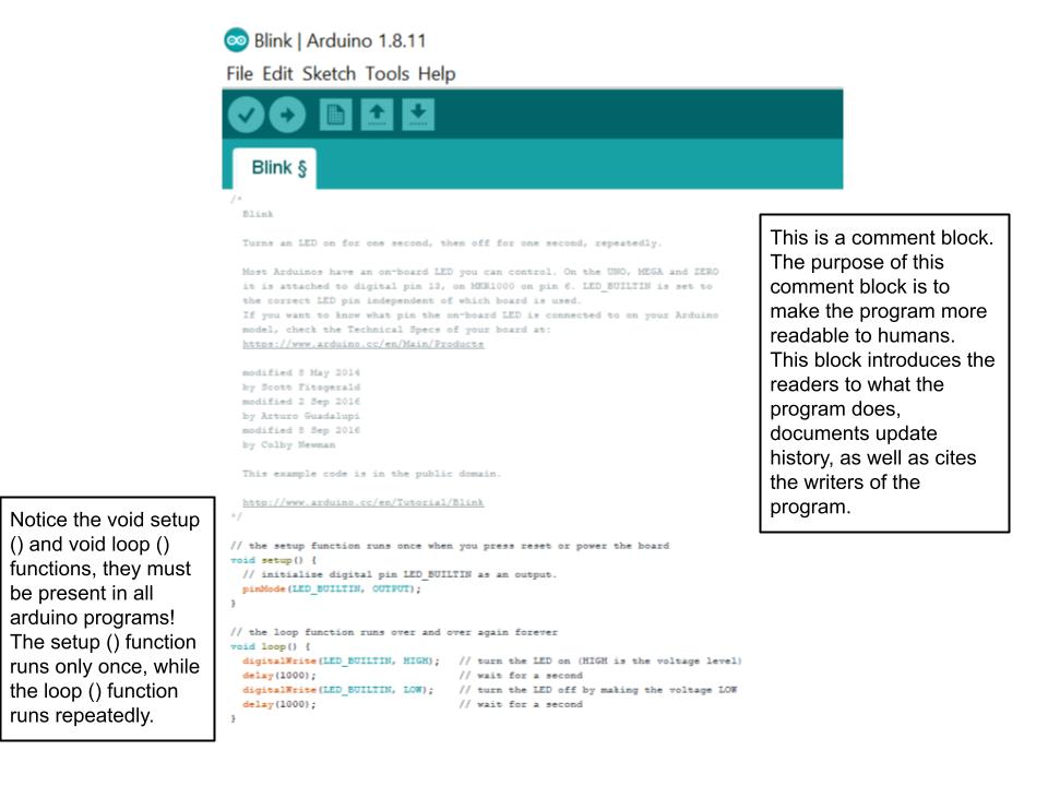
The Arduino IDE provides creators with a plethora of written programs that are fully ready to run on an Arduino board. They are located in the Files>Examples folder. Among the most basic is the "Blink" program, which can be used to not only get to know the basic features in the software and the hardware, but are also a great way to test the connectivity between the Arduino board and the user's computer. This program is located in Files>Examples>01.Basics>Blink.
The following provides an overview of the different functions used in this program:

| Function | Description |
|---|---|
| Setup() | Performs any actions that are initially required to run the rest of the program, such as initializing any peripheral components and setting the communication frequency between the Arduino and the PC. |
| Loop() | The loop function acts as the program's driver, it runs on a continuous loop and specifies the order of operation the microcontroller will perform. Execution starts at the top, goes through the contents of the loop and then starts executing from the top again. This procedure is repeated forever. |
| pinMode (pin number, INPUT or Output) | Configures the pin to behave as either an INPUT or an OUTPUT. |
| digitalWrite (pin number, HIGH or LOW) | Writes a HIGH or LOW value to a digital pin. If the pin has been configured as an OUTPUT, then the signal sent over (ie the voltage) will be set as 5 V (HIGH), or 0 V (LOW). For 3.3 V output boards, the high value will be set to 3.3 V, whereas the low is the same as the 5V board, which is 0V. |
| Delay (time in milliseconds) | Pauses the program for the amount of time specified in the parameter. |
Initializing a Pin as an Input or Output
When using components you will often have to initialize the pin they are connected to as either an input or output! The syntax for this will vary depending on the component and what pin type it is connected to.
Analog Input/output
When trying to manipulate data from an analog pin, the following lines of code are used to read data from it:
int variable = analogRead(insert pin number); //here a variable is being defined to hold the value read from the pin
When you want to write data to the pin the following syntax is used:
int variable = analogWrite(insert pin number); //here a variable is being defined to hold the value read from the pin
Digital Input/output
When wanting to use a digital pin you will need to declare as either an input or output in the Void Setup () as follows:
pinMode(LED1, OUTPUT); //For example if you had a pin called LED1
When wanting to write a value to LED1 then you would use the following syntax:
digitalWrite(LED1, HIGH); //Here HIGH or LOW would indicate if you would like the led to turn on - for turning it on you set HIGH, and LOW otherwise.
Some other basic considerations:
| Symbol | Description | |
|---|---|---|
| Brackets | {....} | Starts and ends a function or is used to group different statements together |
| Comment bars | /* ….*/ or // | Allows coders to add comments to their code to make it more readable to other humans. Important to note that all comments do not get executed by the program and therefore do not alter the program! |
| Semicolon | ...; | This character ends a program statement and lets the compiler know ‘the end of the current line/statement’ |
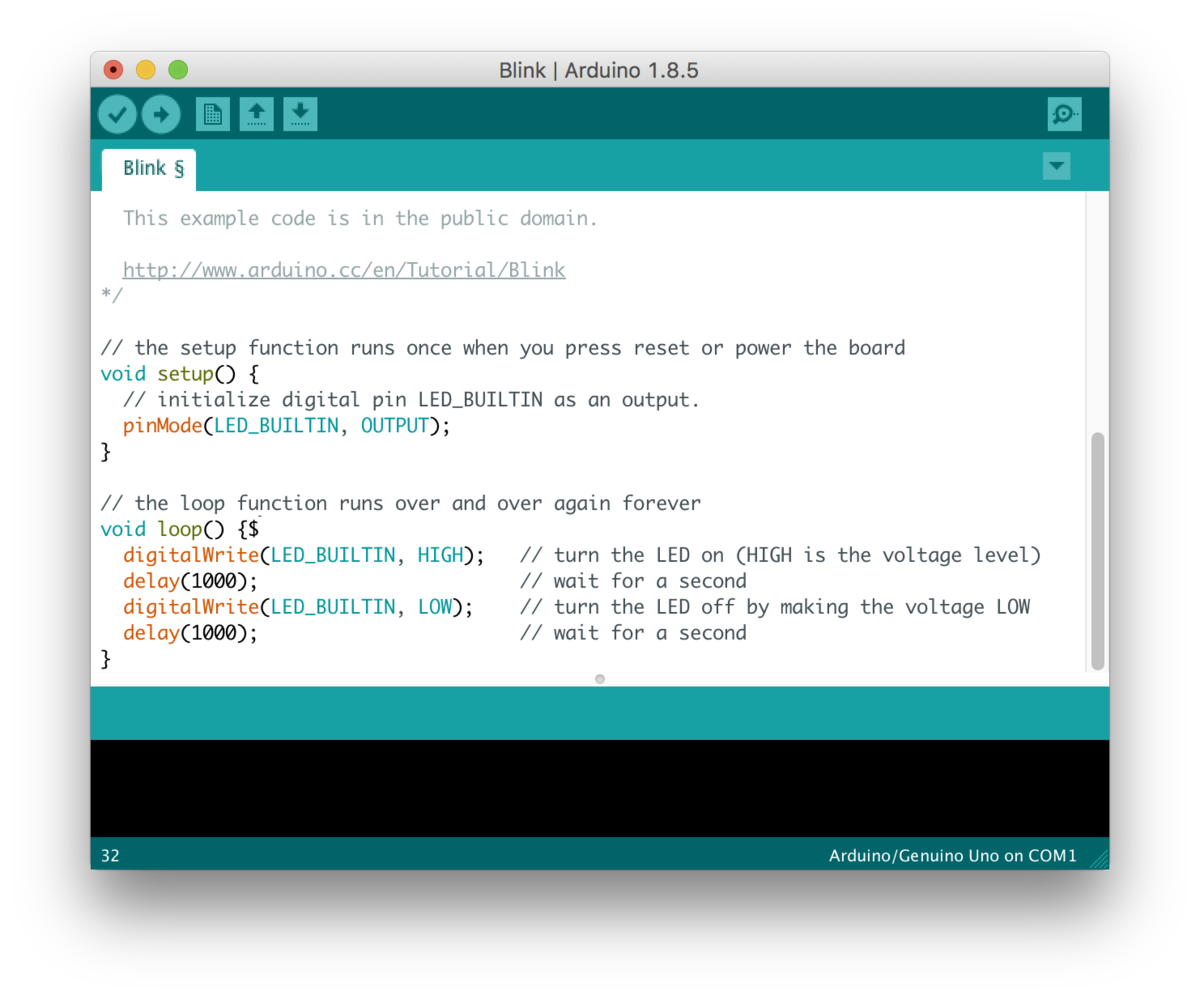
It is also important to be aware that the Arduino editor is case sensitive, meaning that the words “DOOR” and “Door” are not understood to be the same word by the compiler. Furthermore, to make writing and editing code more friendly, the Arduino IDE will colour code important functions, comments, etc. This will be seen later in this section.
As seen below, certain preexisting functions in the Arduino IDE will often times be a certain colour. This is a good indicator of if whether or not you have written the function correctly.

Pseudocode and Flowcharts
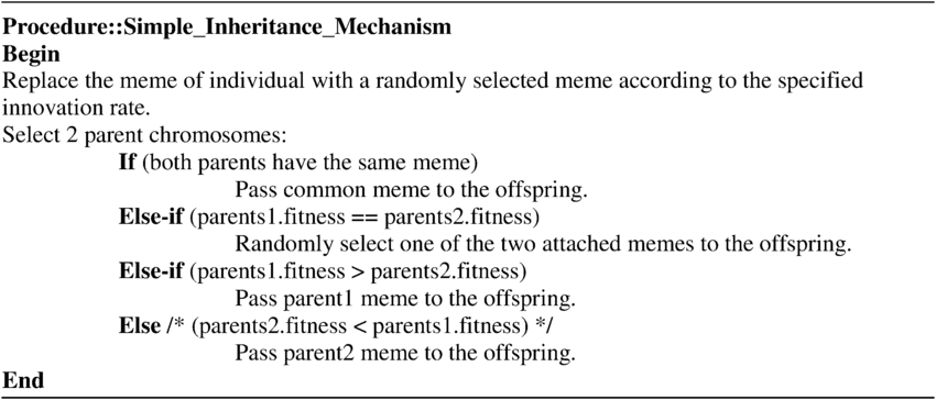
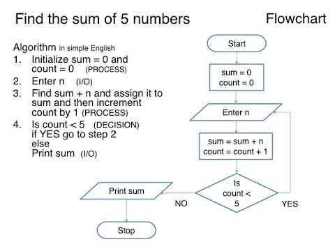
As the complexity of your projects progress keeping track of all the different functions will likely become increasingly more difficult. Some tools that are often used to help create a layout of what the purpose of the programs is include pseudocode and flowchart. They both aid in visualizing and outlining the logic behind your code, the difference between the two is that flowcharts are more visually based and in contrast pseudocode is a typed-up outline of the code [refer to examples below].


This allows the designer (you) to be able to work through the logic behind the code before creating it, allowing for a far smoother design process.