Difference between revisions of "Digital technologies/Arduino/Arduino- Beginner/Understanding Arduino Boards"
(Created page with "{{#lsth:Digital technologies/Arduino/Arduino- Beginner|Understanding Arduino Boards}}") |
(No difference)
|
Latest revision as of 18:11, 25 July 2022
What is a Micro-controller?
A micro-controller is a compact integrated circuit that receives input from the environment, processes the input and can produce an output. It receives input from its I/O pins and processes the signals received using the CPU onboard the chip. Micro-controllers are usually embedded in larger systems and are utilized in many areas of life including vehicles, medical devices, home appliances, and more.
Arduino is an open source electronics platform that provides an easy and accessible way to make robotics projects. The boards are able to receive input signals from sensors and can produce outputs through I/O pins. Arduino boards are used by a diverse set of people, including students, hobbyists, engineers, researchers due to the simple layout and programmability of the Arduino boards.
An Arduino or microcontroller can be implemented in many ways:
Arduino board sections
There are 5 important board sections that the user must have a solid understanding of to start utilizing the board's functions. These sections are outlined below:
| Section | Description |
|---|---|
| USB connector | The arduino can be powered through a type A/B USB connector from the user’s laptop/computer to the board. This port is also used to upload programs onto the board. |
| Power port | The arduino board can be powered through an AC-DC adapter or a battery. The power jack of the board can be connected to a 2.1 mm center-positive plug. |
| Power pins | To power external circuitry, 3 standard voltages (0 V or GND, 3.3V, 5V) are provided in the ‘Power Pins’ section of the board. |
| Digital pins | Digital pins on the arduino board can be configured as an input or an output. When the pins are configured as an input, the pins will send a binary signal into the board, which enables the board to read the sensed logic voltage levels (ie. either 0/low or 1/high). If the digital pins are configured as an output, then the arduino will send a binary signal to the pin. There is a built-in LED pre-connected to digital pin 13. When the value of the pin is driven HIGH by the processor, the LED on the board is illuminated, when the pin is LOW, it's turned off. This can be used as a status indicator when programs are running. |
| Analog pins | The analog pins allow the arduino board to receive or send an analog signal. These signals need to be converted into digital representations which can be used inside the software-executing portion of the Arduino processor (which only uses binary digital signals). Analog signal inputs can be accepted for conversion into digital via the Analog Pins header. The Analog to Digital (A/D or “A to D”) conversion is done inside the processor with specialized circuitry. |
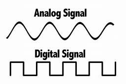
Analog VS Digital signals
A signal is an electromagnetic or electric current that transfers information from one source to another. There are two main types of signals used in electronics: analog or digital signals.

Analog signals
This is a time-varying and continuous type of signal that is often used to measure changes in light, sound, position, temperature, or other physical phenomena. When plotted in a voltage-time graph, the result is often a continuous and smooth curve.
Digital signals
A digital signal is a signal that represents information as a series of discrete binary values. Digital signals are used in all modern electronic applications, including communication and network devices. When plotted in a voltage-time graph, the signal is discrete, and ranges from 0 V to VCC (usually 1.8V, 3.3 V, or 5V).
Connecting to an Arduino
- There are a few ways that you can ruin or burn your Arduino, refer to this guide before starting for more information.
- If you are using a lab computer in the Faculty of Engineering refer to this guide for additional steps to connect the Arduino.
Step 1: Download the Arduino IDE from https://www.arduino.cc/en/software. Make sure to choose the version that is appropriate for your operating system.
Step 2: Connect the Arduino to your computer via an A/B type USB cable.
Step 3: Once the Arduino is connected, your computer will recognize the Arduino board as a generic COM port. The power LEDs onboard the Arduino should light up.
Step 4: Time to find out what port number is assigned so that the Arduino and computer can properly communicate with one another. in the IDE select Tools > Ports > Select a port. If even after selecting the port the Arduino doesn't connect, try a different port.
Step 5: Open the Arduino IDE. Under Tools>Board, ensure that the correct type of Arduino board is selected.
Step 6: Under Tools> COM, ensure that the “port” is the one shown in the step above. Check that the programmer is set as “AVRISP AKII”
Possible bugs:
If you're having trouble with your Arduino, refer to this guide: Arduino troubleshooting
