Breadboard
Breadboard
When you start your journey on electronics, you will eventually need to wire different parts to each other. Chances are, you will be requiring a breadboard to do it.
What is a breadboard?
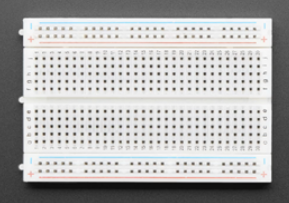
A breadboard is a simple device designed to allow you to easily create electronic circuits without the need for soldering. This device is great for the quick creation (prototyping) of temporary electronic circuits or to carry out experiments and tests on circuit design. Breadboards are made out of plastic and have metal connectors inside. They come in various sizes, and the design can vary, but as a general rule they look something like this:
Now, why is it called a breadboard?
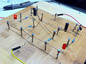
Before the 1970s, electrical engineers did not use tools such as Solderless breadboards as we use today. Instead, they would build electronic circuits by hammering nails and screws into wooden boards. These boards we typically bought from hardware stores for convenience which were often literal breadboards. The engineers would wrap the wires around the nails along with the other various electrical components, then glue and solder them together assuring a secure electrical connection.
Back then, the electrical components were much larger and the circuitry was simpler. This being said, it would not be easy to create a complex circuit using this method as there would be wires possibly touching. Also, the modern PCB takes up fractions of the space of a pre-1970 breadboard would in an electronic device. Nowadays, breadboards are made out of plastic and have metal connectors inside.
How do Breadboards work?
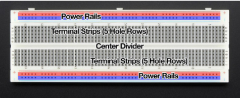
The breadboard has lots of little holes in it, and these holes are connected to each other in certain ways. There are two long rows on the sides of the breadboard, these are called the power rails. The holes in the power rails are connected to each other, so you can use them to provide power to your circuit. The power rails have a + sign to indicate the positive side and a - sign to indicate the negative side. The rest of the holes in the breadboard are in groups of five and are connected to each other in a row. So, if you put a component (like an LED or a resistor) into one of those holes, it will be connected to the other holes in the same row. This allows you to build a circuit by connecting different components together.
So, in short, a breadboard is like a big plugboard that allows you to build a circuit without soldering. The power rails provide power and the other holes allow you to connect different components together to make the circuit work.
Step by step on how to use a Breadboard
LINK
- Gather all necessary components: To begin, gather all the necessary components such as a breadboard, wires, and electronic components (LEDs, resistors, capacitors, transistors, etc.).
- Insert electronic components into the breadboard: Start by inserting the electronic components into the breadboard. Make sure to insert the components into the correct row and column. Most breadboards have two columns of power rails, one for positive voltage and the other for negative voltage, and a grid of holes in the middle that are connected internally in rows and columns.
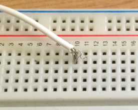
- Connect the electronic components using jumper wires: Use jumper wires to connect the positive and negative terminals of the components. The negative terminal is typically indicated by a black or white stripe, while a longer lead typically indicates the positive terminal. The jumper wires can be inserted into the holes of the breadboard, making sure that the wires are inserted into the same row as the component terminals.
- Incorporate any necessary resistors or other components: If you are using an LED, include a resistor in the circuit to prevent the LED from burning out. Also, If you are using any other components like capacitors, transistors, etc. make sure to connect them properly as per the circuit diagram.
- Power the circuit: After all the components are inserted and connected, you can now power the circuit using a power supply such as a battery or a DC power adapter. The positive voltage rail should be connected to the positive terminal of the power supply, and the negative voltage rail should be connected to the negative terminal of the power supply.
- Test the circuit: Test the circuit by turning on the power and observing if the components are functioning as expected. If the circuit is not working as expected, check for any loose connections or reversed polarities.
- Disassemble the circuit: Once you are done with the circuit, turn off the power and carefully remove all the components and wires from the breadboard. It is important to be gentle and not pull the wires out of the breadboard as it may damage the connections inside the breadboard.
- Store the components and wires properly: Finally, store the components and wires properly for next use. Make sure the components and wires are clean and dry before storing them. This will help to prevent any damage and extend the lifespan of the components.
Wire jumpers
Breadboards have many small connections inside them, but they only go in rows or in columns, so each pin or wire in a part has 5 total connection points. To wire the parts, you need to connect the parts using different wires. The following here are the pros and cons of each of the possible options:
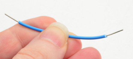
- Stranded
- Stranded wire is made up of many thin wires that are twisted together. It is flexible and can be easily bent, making it ideal for use in situations where the wire needs to be moved frequently. However, it can be more difficult to work with because the individual strands can break if not handled carefully.
- Solid core wire
- Solid wire is made up of a single piece of wire and is less flexible than stranded wire. It is easier to work with because it does not have individual strands that can break, but it can be more difficult to bend and shape.
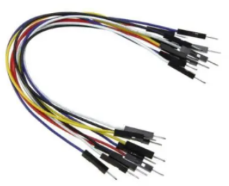
- Jumper wires
- Jumper wires are short, pre-formed wires with connectors on each end that are used to make connections on a breadboard. They come in different lengths and colors, and they are specifically designed to work with breadboards. They are easy to use and can save time when connecting components on a breadboard.
Tips for neat/reliable breadboarding
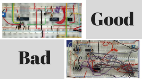
- Plan ahead: Before you start building your circuit on the breadboard, take the time to plan out the connections and components you will need. This will help you to avoid mistakes and make the breadboarding process more efficient.
- Keep it organized: As you build your circuit, keep the components and wires organized and tidy. This will make it easier to troubleshoot any issues that may arise.
- Pay attention to polarity: Many components, such as LEDs and diodes, have a specific polarity and must be inserted into the breadboard with the correct orientation. Make sure to pay attention to the polarity of the components you are using.
- Label your connections: As you build your circuit, make sure to label your connections. This will help you to keep track of the different parts of your circuit and will make troubleshooting much easier.
- Test as you go: Test your circuit as you build it to ensure that everything is working correctly. This will help you to identify and fix any issues early on in the process.
