Digital technologies/Vacuum Forming
Vacuum forming is a manufacturing method used to shape a heated sheet of plastic around a certain mold using the force of a vacuum. It's great advantage is fast production of parts with minimal post processing. There are different methods to vacuum forming. The mold, also called the tool, can be either male or female. Male tools are used if precision is needed on the inside of the part. Female tools, often used with plugs, are used for precision on the outside of the part. Most industrial molds are machined from metal blocks, such aluminum. Although, the use of machined molds can get expensive as they are hard to make and can have a long lead time. If the tool needs replacing or modification, it can create a lot of down time. This is where 3D printed molds come in handy. They are not as durable as machined molds, but are ideal for fast prototyping. The complication with 3D printed molds is that filament is also a thermoplastic, which melts under heat. So how do you keep the integrity of your mold when in comes into contact with a very hot plastic sheet? This is what we will be covering in this document as to how to prepare your molds to perform as best as possible in the vacuum forming process.
3D Modeling your Mold
To succeed at vacuum forming it starts way before using the machine. A good mold is the foundation of a good part, with as little complications along the way.
Draft Angles
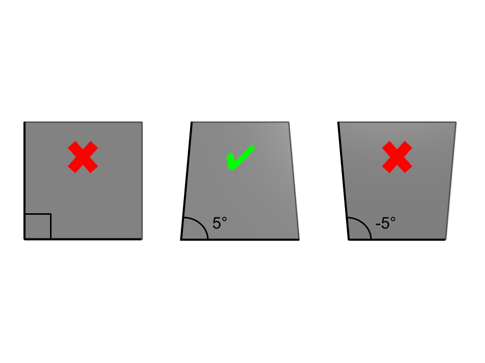
When vacuum forming your part, you want to avoid your mold getting stuck into it. To avoid this issue, we implement draft angles to all sides of the 3D model to ease the release of the mold. The recommended angle is 5° to 7° for male molds and 2° to 3° for female molds.
Undercuts
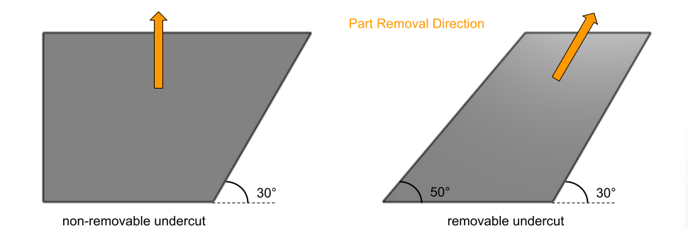
Similarly to the reason we apply draft angles, we avoid undercuts to prevent the risk of our mold getting stuck. A good way to avoid them is to ask yourself if your 3D part needs supports. If it does, then chances are that your mold will get stuck in your vacuum formed part.
Possible Depths
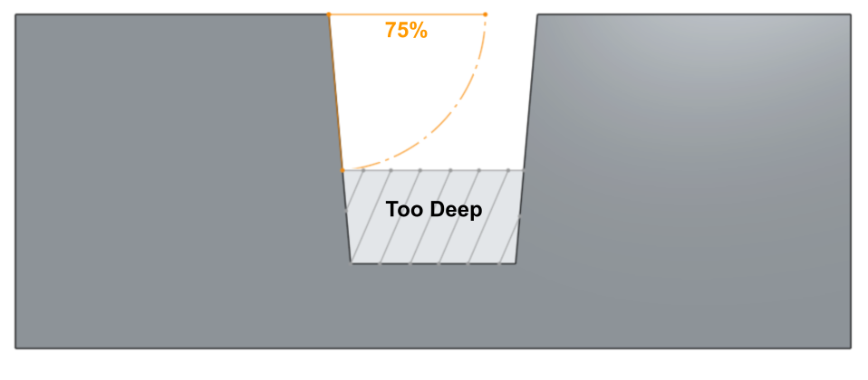
A plastic sheet only has a certain amount of material available to form a mold. There is a limit to the amount a material is capable to draw. There are formulas and guidelines available to determine that limit. When it comes to cavities, the maximum depth should not exceed 75% of the opening.
Draw Ratio
Similarly as cavities, there is a maximum height you can have with your mold for a given sheet thickness. If you want your wall thickness of your final part to be a certain thickness, then you will use the draw ratio to find out which sheet thickness is best suited for your project. Here are the steps to calculate the draw ratio:
- Step 1: Calculate the surface area.
Using a CAD modeling software, you can easily get the surface area of your mold. If you do not have the exact number, you can approximate it by taking general measurements and assuming it as a simple geometry.
-Step 2: Calculate the footprint.
The footprint is the heated area of the plastic sheet and can be easily found if you know the dimensions of your machine.
-Step 3: Calculate the draw ratio.
To find the draw ratio, divide the surface area by the footprint.
Whichever number you end up with, you can multiply it by the desired wall thickness to find the starting gauge of your plastic sheet.
Edges / Fillets
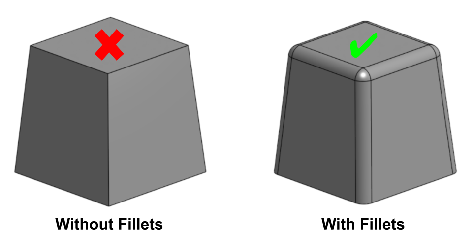
Whenever you create a part for vacuum forming, you want to avoid sharp edges or sharp angles as much as possible. The thicker your plastic is, the less capable it will be to take the shape of those sharp corners. The thinner the material is, the more susceptible it is to overstretching.
Air Holes
For the plastic sheet to be able to take the shape of your mold, air needs to be able to escape from between them. To help achieve so, we implement air holes at strategically placed locations. In general, these locations imply any area that is lower than it's surrounding such as cavities, where an air pocket can easily be formed. It is ok to add air holes directly in your 3D model but it will increase print time unnecessarily. It is recommended instead to drill the holes manually with the correct drill bit size and protective gear. Visit the VAQUFORM page where they talk more in depth about air holes.
Printer Settings
Once your 3D model of your mold is complete, it is time to print it. This is the part where slicer settings and filament selection will help the most towards the durability of your mold. Visit the VAQUFORM page for a detailed explanation on how to make your prints.


