Digital technologies/3D printing/3D modeling- Intermediate/CAD Extensions
In the beginner section of 3D modeling, you were introduced to TinkerCAD. In the instructions, you were instructed to export your 3D designs as a STL or OBJ file. In this section, the differences between different CAD file formats will be discussed.
Standard Triangle Language (*.STL)
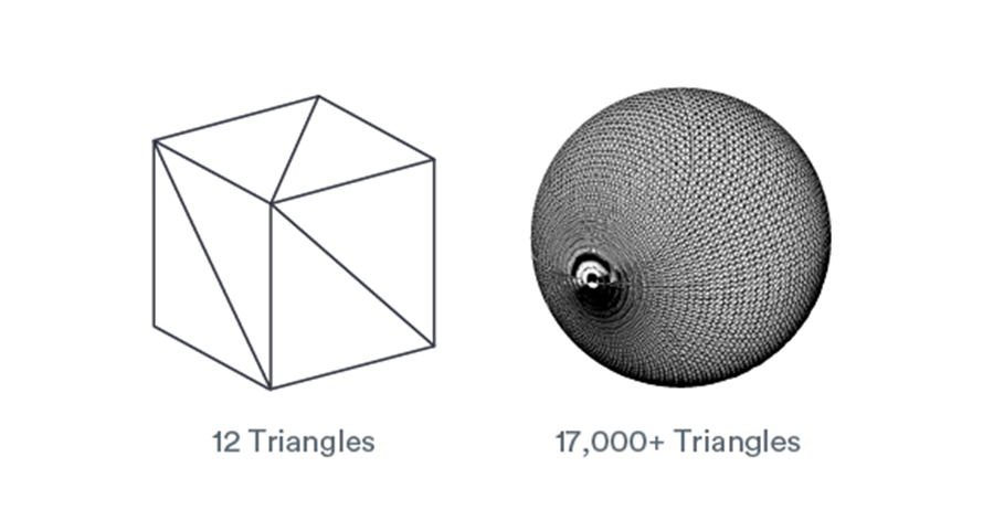
STL files are the most used file format in 3D printing and 3D modeling. Most 3D printers support the file format. Many of the 3D printable models online are also found in STL file format. STL stands for stereolithography, a 3D printing process created at 3D Systems in the 1980s. STL file format encodes the surface geometry of a 3D object. This is done through tessellation, a process of tiling a surface with one or more geometric shapes so there are no overlaps or gaps. The basic method of tessellating the outer surface of 3D models is through the use of tiny triangles (called “facets”) and store information about the facets in a file. For example, in the figure below, it shows how a cube can be represented by 12 triangles while 17000+ triangles are needed to represent a sphere. Since triangles consist of three straight edges, it can be difficult to approximate curved geometries. To do so, mesh density is increased, and individual triangle’s size is decreased.
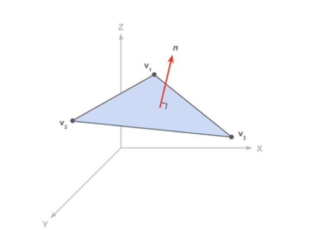
STL file format stores the information as the coordinates of the vertices and the components of the unit normal vector to the triangle. The normal vector point outwards of the 3D model.
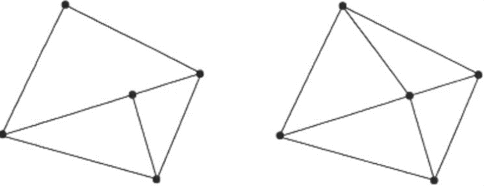
There are a couple of rules for tessellation and storing information. The vertex rule states that each triangle must share two vertices with its neighbouring triangles.
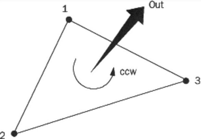
The orientation rule states that the orientation of the facet must be specified in two ways. The direction of the normal should point outwards, and the vertices are listed in counter-clockwise when looking at the object from the outside.
The all-positive octant rule states that the coordinates of the triangle vertices must all be positive. This ensures that all coordinates stored would be in the positive which would save space in the file. Finally, the triangle sorting rule recommends that the triangles appear in ascending z-value order. This is a recommendation rather than a rule as it helps the software slice the models faster.
Wavefront OBJ (*.OBJ)
OBJ is a crucial file format in 3D printing. It is generally preferred for multi-colour 3D printing. Often, it is used a s an interchange format for non-animated 3D models. OBJ file format stores information about 3D models by encoding the surface geometry of the model. It also stores information about its colour and texture. It does not store any data about animations or scene. It is open source and neutral. Therefore, it is often used to share 3D models since many CAD software supports the format.
It differs from STL since it stores colour and texture information. STL is an older file format that is missing modern features. It does not support multi colour printing or high resolution prints. OBJ can approximate surface geometry well without drastically increasing the file size. It also supports multiple colours and textures in the same model.
OBJ encodes surface geometry of a 3D object in many different methods: Tessellation with polygonal faces, freeform curves and freeform surfaces. Similar to STL, OBJ allows tessellation of the surfaces with simple geometric shapes like triangles or more complex polygon. This is the simplest way to describe surface geometry. However, approximating curved surfaces with polygons will introduce coarseness and geometric deviation from the model. The size of the polygons can be decreased to increase the quality of the prints. However, this can lead to giant file sizes which can be difficult for 3D printers to handle. It is important to find the right balance between print quality and file sizes.
The surface geometry can also be defined using freeform curves. The user defines a collection of free form curves that runs along the surface of the model. The surface is then approximated using the collection of curves. It is more complicated than polygonal faces, but it allows for fewer data to describe the same surface. The curved lines can be described using freeform curves with a few mathematical parameters. It allows for higher quality encoding without drastically increasing the file size.
DS Solidworks Parts (*.SLDPRT) and DS Solidworks Assemblies (*.SLDASM)
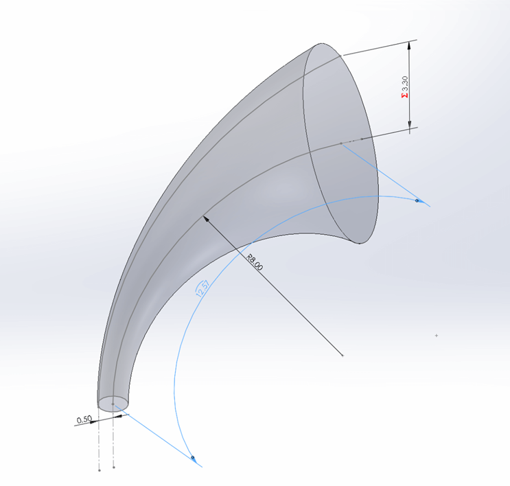
Sldprt file formats are native SolidWorks file extensions. It provides details on specific parts within a system. This is a software specific file format. Opening SolidWorks files in slicers and other software may cause some corruption of your designs. However, because it is software specific, it contains the most information about your models. As such, you should do all your modeling while the files are in native format
ISO10303 - Standard for the Exchange of Product model data (*.STP, *.STEP)
STEP file format is a neutral file format. It is the most common file format used to share 3D designs. This allows users to open others’ designs using the software of their choice. It stores 3D images in an ASCII format. While STEP files can be opened with most CAD software. It is not easily edited. The model will display as a finalized object. Users cannot edit specific dimensions or features of the model.
Polygonal Formats
NURBS Formats
Standard
- ISO10303 - Standard for the Exchange of Product model data (*.STP, *.STEP)
- AutoCAD Drawing Exchange Format (*.DXF/*.DWG)
- Initial Graphics Exchange Specification (*.IGES) (standard last updated 1996)
Software-Specific
- DS Solidworks Parts (*.SLDPRT)
- DS Solidworks Assemblies (*.SLDASM)
- DS CATIA V5 Parts (*.CGR/*.CATPart)
- DS CATIA V5 Assemblies (*.CGR/*.CATProduct)
- PTC Creo Parts (*.PRT)
- PTC Creo Assemblies (*.ASM)
- Fusion 360 (*.F3D)
It should be noted that Fusion360 stores files on the cloud, such that locally saved .f3d files are not commonly encountered. It should also be noted that OnShape does not have a file format given it is hosted entirely on the cloud.