Difference between revisions of "Digital technologies/3D printing/3D modeling- Intermediate"
| Line 99: | Line 99: | ||
It should be noted that Fusion360 stores files on the cloud, such that locally saved .f3d files are not commonly encountered. It should also be noted that OnShape does not have a file format given it is hosted entirely on the cloud. | It should be noted that Fusion360 stores files on the cloud, such that locally saved .f3d files are not commonly encountered. It should also be noted that OnShape does not have a file format given it is hosted entirely on the cloud. | ||
| − | == Using Parametric NURBS Software == | + | == [[Digital technologies/3D printing/3D modeling- Intermediate/Using Parametric NURBS Software|Using Parametric NURBS Software]] == |
===[[Digital technologies/3D printing/3D modeling- Intermediate/Using Parametric NURBS Software|Introduction to Fusion360]]=== | ===[[Digital technologies/3D printing/3D modeling- Intermediate/Using Parametric NURBS Software|Introduction to Fusion360]]=== | ||
Revision as of 20:53, 4 June 2024
TinkerCAD is nice for smaller parts with very little complexity. However, since it is not NURBS based nor parametric, it lacks major functionality. It is strongly suggested at this stage that TinkerCAD, Blender, Cinema 4D or other polygonal modelling (non-NURBS) applications be set aside for parametric CAD software, such as Autodesk Fusion 360 (free for students. teachers, and educators), Dassault Systèmes Solidworks (available through Remote Apps) or PTC OnShape (completely online, free for students and educators) be used for mechanical design, as models made with such software contain much richer data that allows going from CAD models to manufacturing data. Polygonal modelling remains, however, an important tool for Scan to CAD, and such the intermediate CAD user should have a complete understanding of polygonal modelling software such as TinkerCAD.
Complex Shapes in TinkerCAD
In the beginner section of 3D modeling, you learned how to group shapes together. In advanced TinkerCAD, you will use the skills you have gained to create more complex shapes. TinkerCAD provides you with basic geometries such as cubes and cylinders. You can combine these shapes to create more complex geometries such as a house using the group function. To create even more complicated designs, you can combine shapes to be used to create complex holes
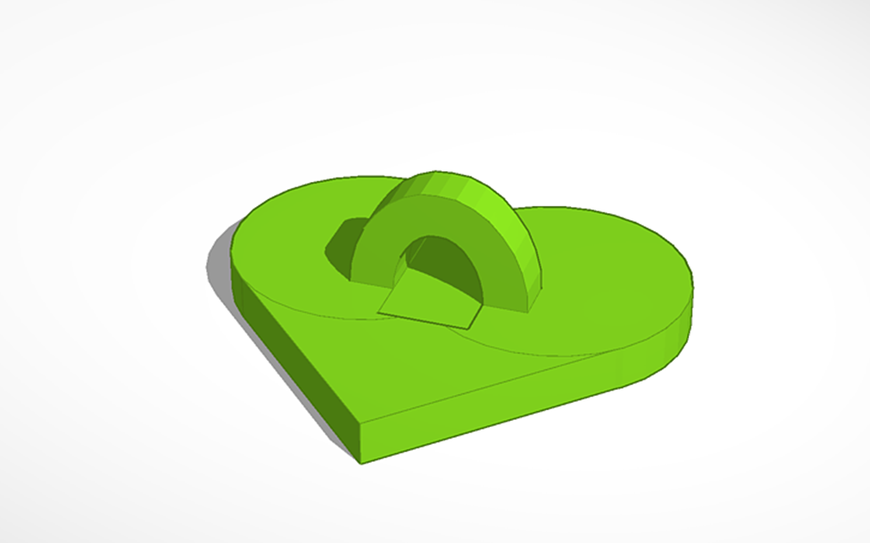
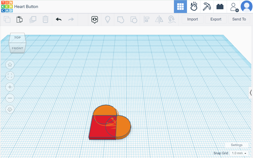
The example below will walk you through the making of a heart button. It will involve grouping shapes together in order to create a more complex shape and feature
- Add a box shape to the workspace. Make sure the dimension of the box has the thickness of the desired button. This will serve as the point of the heart.
- Add two cylinders with the same thickness as the box to two edges of the box. Set the diameter of the cylinder as the width of the box. This will create the humps of the heart.
- Using the round roof object, size it to the appropriate dimension for the button hoop.
- Copy and paste
ra second round roof object and make it slightly smaller to be used to create the hole for the button hoop. - Turn the object into a hole and position it accordingly.
- Finally, group the shapes together and the button is completed.
Design for 3D Printing
There are some important things to note when modeling for 3D printing. It is important to optimize the print by decreasing print time and material while ensuring accuracy and strength of the part.
- Divide your model into smaller more manageable parts. There are many designs with complex details or large dimensions that would be more manageable prints if split into multiple parts.
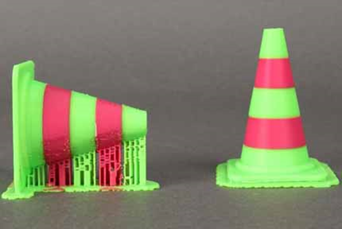
- Try to ensure that there is one flat surface on the print. This will allow easier print set-up. The flat side can adhere to the build plate, minimizing the need for additional build plate adhesion.
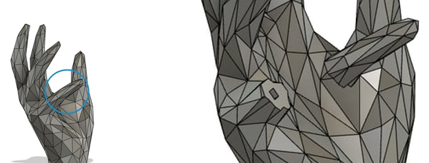
- Avoid floating parts. All aspect of the model should be connected to the main model. Minimize overhangs in the model as well. This will prevent wasted time and material to print supports.
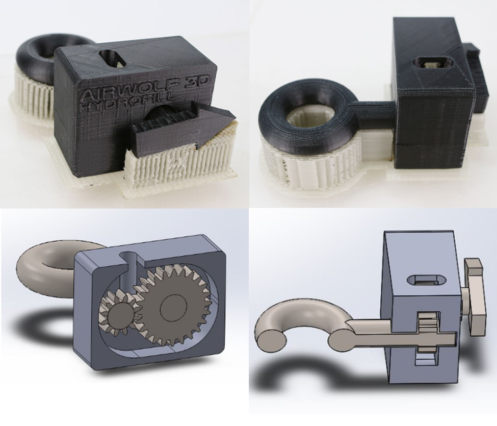
- FDM printing has limited capabilities with dimensional accuracy. It is recommended to prevent printing horizontally oriented holes of the smaller size. These holes are often deformed and printed with difficult to remove supports.
- Printed parts are stronger in one direction than another. It is important to keep this in mind when designing. Prints will be weaker in the areas where the layers meet. This means that printed parts have low tensile strength along the Z-axis. The prints will be the strongest in planes parallel to the build surface.
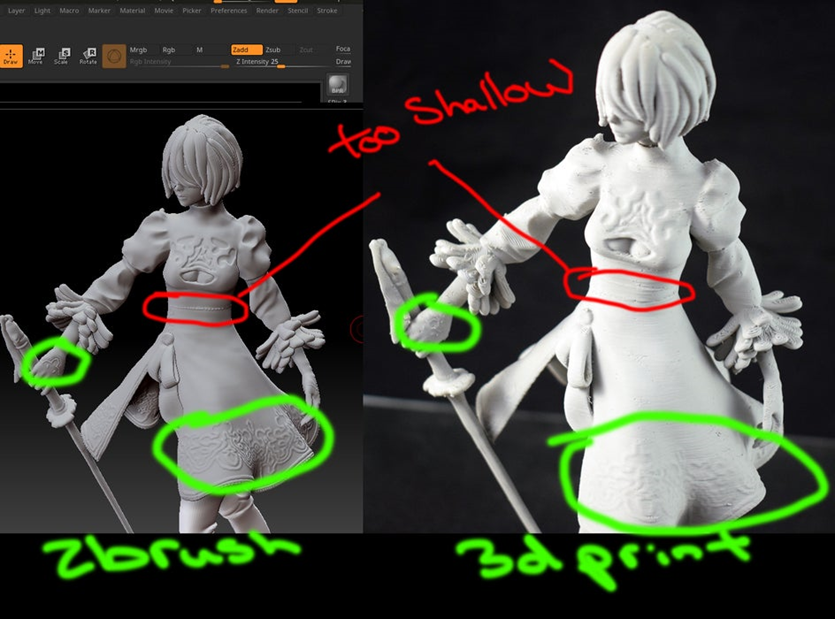
- Exaggerate the details of your designs. This is an important thing to keep in mind. In order for details to show up on small designs, you should make your cuts deeper and bigger. It can also be helpful to make slender designs thicker.
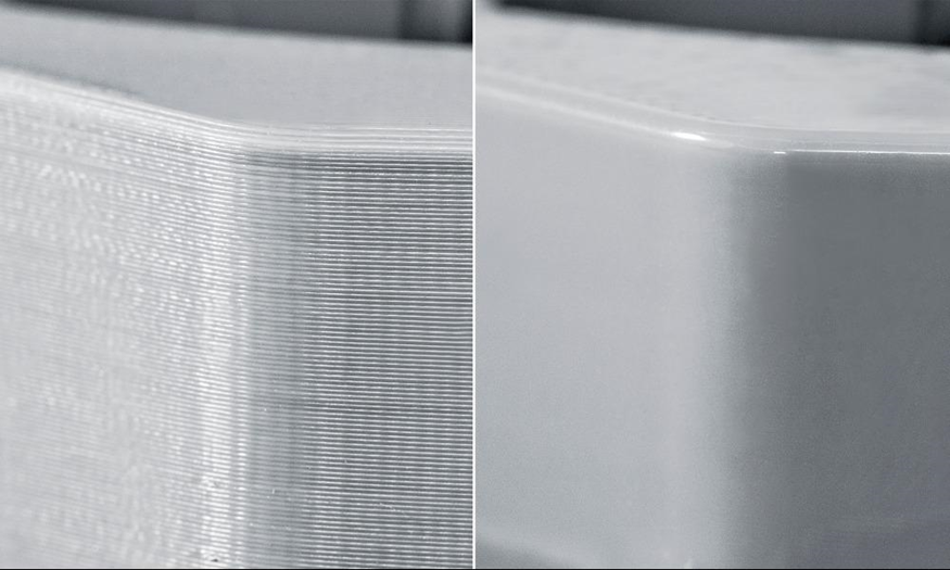
- Round surfaces will not show up smoothly. Since FDM prints in layers, it will cause the rounded surfaces to look jagged. To achieve a smooth surface, additional processing will be required.
If your design is to be used in (electro-)mechanical assemblies in which there are interfacing components, it is important that you understand three basic tolerancing concepts and to keep them in the back of your mind when modeling or more generally designing these assemblies.
- Form: The form of a part refers to the overall dimensions and the shape of the exterior surfaces of a component. Think of a flaw referring to form as a print that ended up not matching the base geometry that was used to create it in CAD due to adverse physical variables during the printing process. Examples follow:
- A sphere may end up slightly oval once printed due to improper cooling, etc.;
- A pillar might end up tilted to one side due to improper belt tension between the belt axes, etc.;
- A pin feature might end up too large to fit its mating hole due to the printer outputting too much material when producing the outer walls of the feature (the inverse can also be true).
- Position: Position refers to the distance separating a feature and an (ideally) meaningful reference (i.e.: the distance between a hole and the side of a part, or between two holes). Thankfully, flaws pertaining to position are rare on a properly tuned printer, as the printer does not have any information about existing references other than the build plate. If tuned properly, the printer will always print a feature at a position (X,Y,Z) distance relative to another feature, because that is what the gCode will tell it to do. You can imagine, however, that if the part is warped, the 'build plate reference' is no longer valid, and such, warped parts almost always have features out of position unless the meaningful reference (interfacing feature) used in the design is not the build plate. However, since the build plate reference is such an important one to define the Z position of features (for the printer, that is), making your meaningful reference something other than the build plate does not always guarantee you good positional tolerance independent of warping.
- Surface: The surface finish of a part is a rather complex subject. In 3D printing, and for typical applications of 3D printed parts, it mostly refers to the mean (statistical) difference between the height of cusps and valleys on a part and their deviation from that mean, at a macroscopic level. The most important consideration is that when 3D printing, most surface finishes are quite rough (deviate significantly from the mean), and thus are sanded down considerably to knock out the cusps left by the printer. This post processing can negatively affect the form of the final part.
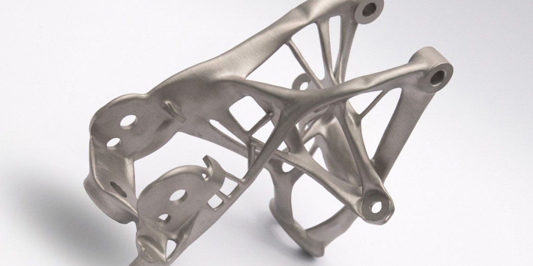
Note that a proper mechanical fit between components demands a good tolerance on form, feature position, and surface finish, such that it is typically impossible to obtain a proper fit when 3D printing, and that if you are considering the 3D printing of critically interfacing components, 3D printing should not be used unless post processing is built into the design. For mechanical designs, you will notice that a main application is brackets. This is because brackets only need good positional tolerance on holes and mating faces, which 3D printing can almost always provide (the tolerance on form for holes is not that important since they are typically clearance holes). However, since some brackets are easily laser cut, 3D printing brackets is only done under certain specific conditions. It certainly has shown its commercial use in cost cutting by replacing intricate multi-part assemblies by generatively designed (we'll say computer generated for now) parts, as shown in the picture below.
CAD File Formats
In the beginner section of 3D modeling, you were introduced to TinkerCAD. In the instructions, you were instructed to export your 3D designs as a STL or OBJ file. In this section, the differences between different CAD file formats will be discussed.
Standard Triangle Language (*.STL)
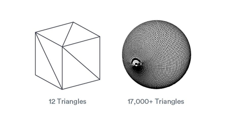
STL files are the most used file format in 3D printing and 3D modeling. Most 3D printers support the file format. Many of the 3D printable models online are also found in STL file format. STL stands for stereolithography, a 3D printing process created at 3D Systems in the 1980s. STL file format encodes the surface geometry of a 3D object. This is done through tessellation, a process of tiling a surface with one or more geometric shapes so there are no overlaps or gaps. The basic method of tessellating the outer surface of 3D models is through the use of tiny triangles (called “facets”) and store information about the facets in a file. For example, in the figure below, it shows how a cube can be represented by 12 triangles while 17000+ triangles are needed to represent a sphere. Since triangles consist of three straight edges, it can be difficult to approximate curved geometries. To do so, mesh density is increased, and individual triangle’s size is decreased.
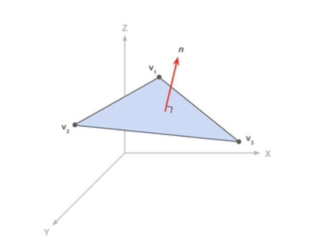
STL file format stores the information as the coordinates of the vertices and the components of the unit normal vector to the triangle. The normal vector point outwards of the 3D model.
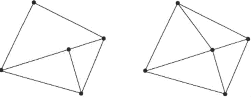
There are a couple of rules for tessellation and storing information. The vertex rule states that each triangle must share two vertices with its neighbouring triangles.
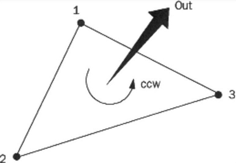
The orientation rule states that the orientation of the facet must be specified in two ways. The direction of the normal should point outwards, and the vertices are listed in counter-clockwise when looking at the object from the outside.
The all-positive octant rule states that the coordinates of the triangle vertices must all be positive. This ensures that all coordinates stored would be in the positive which would save space in the file. Finally, the triangle sorting rule recommends that the triangles appear in ascending z-value order. This is a recommendation rather than a rule as it helps the software slice the models faster.
Wavefront OBJ (*.OBJ)
OBJ is a crucial file format in 3D printing. It is generally preferred for multi-colour 3D printing. Often, it is used a s an interchange format for non-animated 3D models. OBJ file format stores information about 3D models by encoding the surface geometry of the model. It also stores information about its colour and texture. It does not store any data about animations or scene. It is open source and neutral. Therefore, it is often used to share 3D models since many CAD software supports the format.
It differs from STL since it stores colour and texture information. STL is an older file format that is missing modern features. It does not support multi colour printing or high resolution prints. OBJ can approximate surface geometry well without drastically increasing the file size. It also supports multiple colours and textures in the same model.
OBJ encodes surface geometry of a 3D object in many different methods: Tessellation with polygonal faces, freeform curves and freeform surfaces. Similar to STL, OBJ allows tessellation of the surfaces with simple geometric shapes like triangles or more complex polygon. This is the simplest way to describe surface geometry. However, approximating curved surfaces with polygons will introduce coarseness and geometric deviation from the model. The size of the polygons can be decreased to increase the quality of the prints. However, this can lead to giant file sizes which can be difficult for 3D printers to handle. It is important to find the right balance between print quality and file sizes.
The surface geometry can also be defined using freeform curves. The user defines a collection of free form curves that runs along the surface of the model. The surface is then approximated using the collection of curves. It is more complicated than polygonal faces, but it allows for fewer data to describe the same surface. The curved lines can be described using freeform curves with a few mathematical parameters. It allows for higher quality encoding without drastically increasing the file size.
DS Solidworks Parts (*.SLDPRT) and DS Solidworks Assemblies (*.SLDASM)
Sldprt file formats are native SolidWorks file extensions. It provides details on specific parts within a system. This is a software specific file format. Opening SolidWorks files in slicers and other software may cause some corruption of your designs. However, because it is software specific, it contains the most information about your models. As such, you should do all your modeling while the files are in native format
ISO10303 - Standard for the Exchange of Product model data (*.STP, *.STEP)
STEP file format is a neutral file format. It is the most common file format used to share 3D designs. This allows users to open others’ designs using the software of their choice. It stores 3D images in an ASCII format. While STEP files can be opened with most CAD software. It is not easily edited. The model will display as a finalized object. Users cannot edit specific dimensions or features of the model.
Polygonal Formats
NURBS Formats
Standard
- ISO10303 - Standard for the Exchange of Product model data (*.STP, *.STEP)
- AutoCAD Drawing Exchange Format (*.DXF/*.DWG)
- Initial Graphics Exchange Specification (*.IGES) (standard last updated 1996)
Software-Specific
- DS Solidworks Parts (*.SLDPRT)
- DS Solidworks Assemblies (*.SLDASM)
- DS CATIA V5 Parts (*.CGR/*.CATPart)
- DS CATIA V5 Assemblies (*.CGR/*.CATProduct)
- PTC Creo Parts (*.PRT)
- PTC Creo Assemblies (*.ASM)
- Fusion 360 (*.F3D)
It should be noted that Fusion360 stores files on the cloud, such that locally saved .f3d files are not commonly encountered. It should also be noted that OnShape does not have a file format given it is hosted entirely on the cloud.
Using Parametric NURBS Software
Introduction to Fusion360
TinkerCAD is known for its simplicity, meaning it is easy to learn and use. However, its capabilities are limited. It uses a drag and drop method to create basic geometries. Theses shapes can be grouped to create more complex geometries but it takes more time to design something complex and has less flexibility. Fusion 360 is a sketch-based CAD modeling software that allows for users to completely customize their design. It allows users to design 3D objects using 2D sketches.
Fusion 360 offers 3D CAD modeling, PCB design, and 3D simulation capabilities. It is a fee-based subscription software, however, a free version is offered for personal use. The free version has some limited capabilities but most of the 3D CAD features are offered. Even with the limited features it offers more design options than TinkerCAD. To download the software, you can use your AutoCAD account and follow the link below: https://www.autodesk.ca/en/products/fusion-360/personal
Just like TinkerCAD, and with any CAD modeling software you choose to use,. Y you can export your part designs as an STL file. Using this file format, you can use any slicer of your choice to slice the design into a gcode file to print.
Fusion 360 User Interface
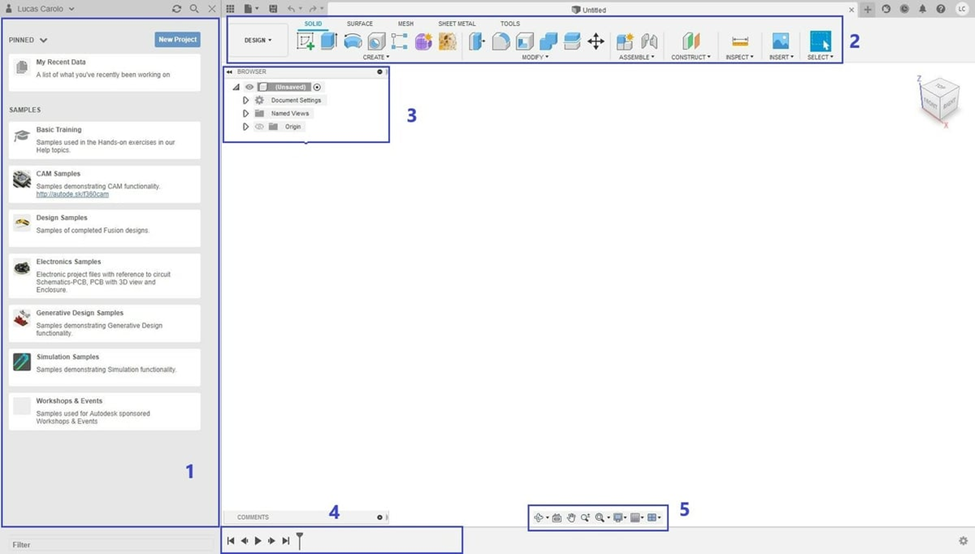
There are 5 main areas of the user interface. When the software is first launched, you should be seeing the screen above.
- Data Panel: On the left is the data panel. It displays pinned and recent projects, providing easy access to these projects for the users. It will also display sample projects that corresponds to the tutorials offered by AutoCAD. Users can also upload their projects to be shared with others for collaboration.
- Tool Bar: On the top of the screen sits the tool bar. Through this, you can use any of the features displayed to manipulate the 3D model you create. The shortcuts can be customized to display the ones you favour.
- Browser: Located at the top left of the main screen. It displays the model design with a file tree structure listing all the components, bodies and constructing plane. The files can be navigated through by clicking on their names. They can also be renamed by double clicking. The files can be collapsed using the triangles. The visibility of the bodies and planes can be toggled by clicking on the lightbulb.
- Timeline: The timeline of the design history is displayed at the bottom of the screen. This is a special feature of Fusion 360 that is different from other CAD software. It keeps a record of the construction of the 3D model allowing the users to playback the building of the model. This feature also allows users to add to the model from a previous state of the model.
- Navigation bar: The navigation bard allows users to change the view of the model. These features exist
sas shortcuts when used with a mouse. For this reason, it is recommended to create CAD models using a physical mouse instead of a track pad. Some features include:- Zoom In/Out by scrolling up/down with the mouse.
- Pan the model by holding down the wheel of the mouse.
- Orbit the model by holding down control + wheel.
Sketching
The sketch function is the most important feature of a CAD program. It allows users to sketch 2D drawings as the base to create 3D objects.
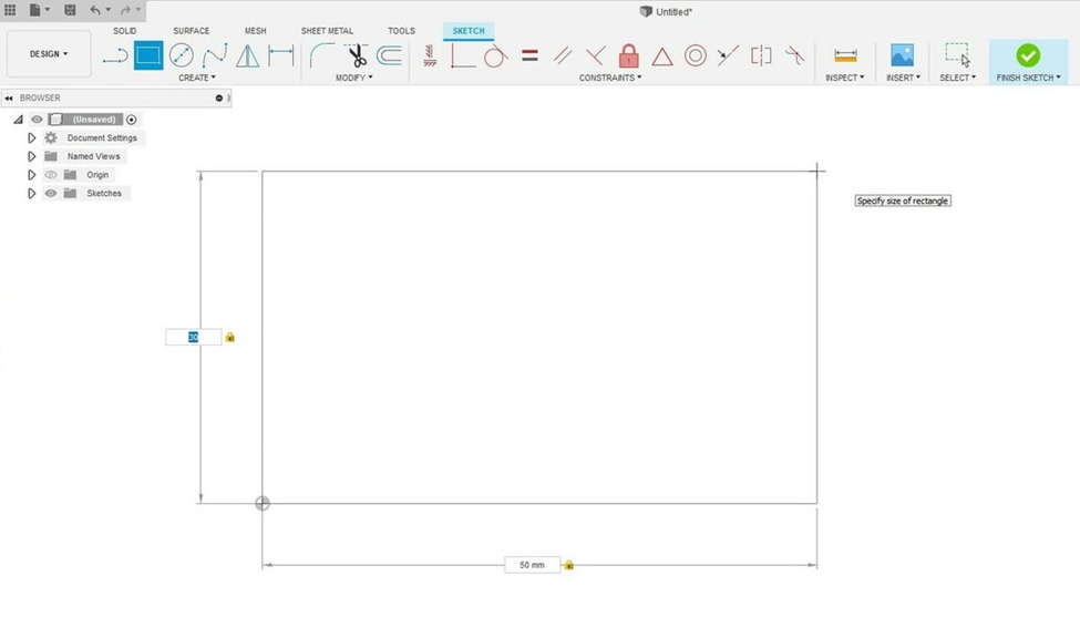
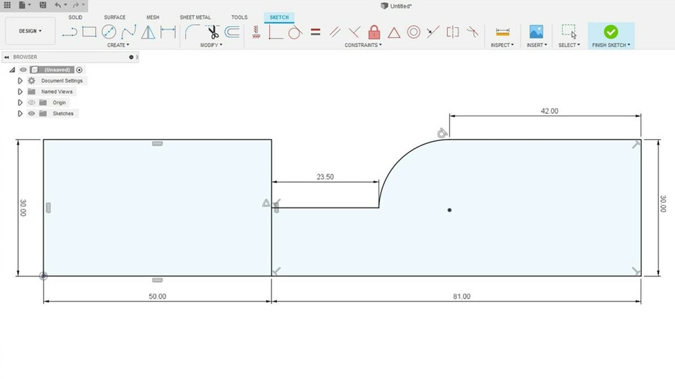
To create a rectangle, first click on “Create Sketch” from the tool bar above. Select the desired sketch plane. In the example above, YZ plane was selected. This is the plane which the 2D sketch will be created. You’ll notice the tool bar above has transformed to display sketch functions. Select “2-Point Rectangle” from the tool bar. Click on the origin of the sketch plane and drag to create a desired rectangle. The sketch features are defined with reference to the origin to position it in space. It is why it is recommended to have one vertex of the sketch to be defined as the origin. After the rectangle is drawn, you can define the dimensions of the 2 sides of the rectangle. You can toggle between the dimensions by using the “Tab” key on your keyboard. Press enter to confirm the sketch.
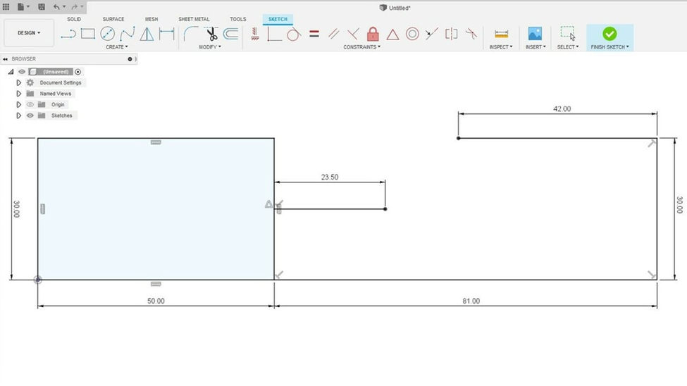
Next, the line tool will be introduced. Drawing a line is the most simple and versatile function of sketch. It will allow you to create any shapes you will need. Select the “Line” option from the tool bar. Hover your mouse over the rectangle, the mouse will be drawn to the line and an ‘X’ will appear. This means that one end of the line will intersect with the rectangle. Move the mouse towards the middle of the line on the rectangle until a triangle icon shows up. This signifies the midpoint of the line. Click to create the start of the line segment. Drag the mouse to create the line and click again to create the end of the line. You can also manipulate the dimension of the line manually by entering the value.
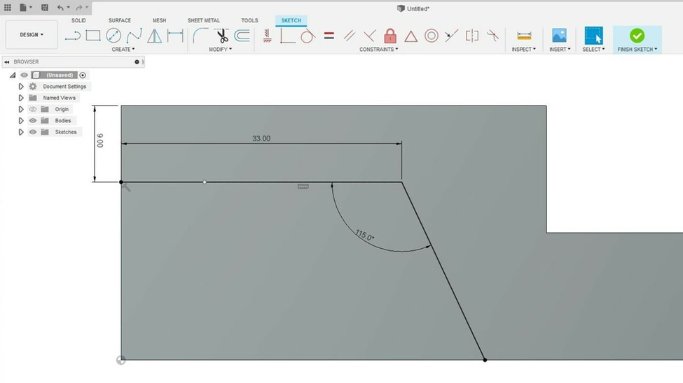
To draw the line at an angle, drag the line out at an angle. At this point, there should be an angle dimension displayed. This value can be altered manually.
To create an arc, select “Create” -> “Arc” -> “Tangent Arc” from the tool bar. This will create an arc tangent to two other entities. Left click on the vertex of where you would like the arc to connect. Then click on the other vertex to connect. Alternative to create arcs include 3-point arcs where you select the two vertex and the middle point of the arc or center point arc when the arc is created by finding the center of the arc.
In order for a 2D sketch to be converted to 3D model, the 2D profile has to be a closed shape. This means all the lines and entities have to form a closed loop. This will be indicated with a light-blue shading inside the sketch.
Extrusion
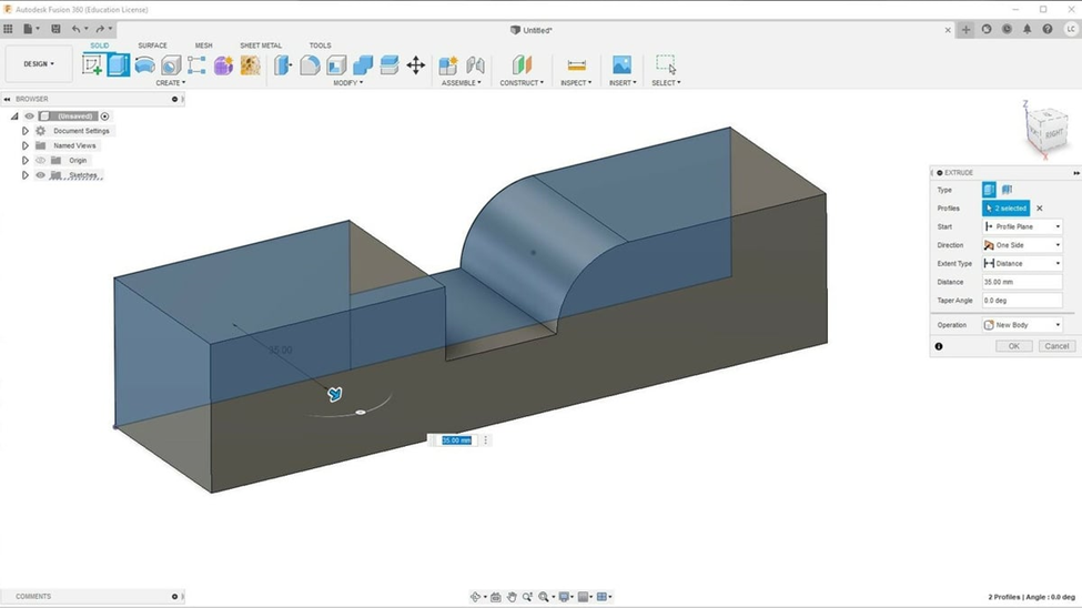
The simplest way to create a 3D model is by extruding a 2D sketch, which adds a third dimension to the 2D sketch. Select “Extrude” from the toolbar. Hover the mouse over the sketch, closed shapes that can be extruded will be highlighted when hovered on. To select multiple shapes, left click on both shapes. In the extrusion settings that pops up on the right, enter the value for the third dimension of the sketch, the width. Click “OK” to confirm the extrusion.
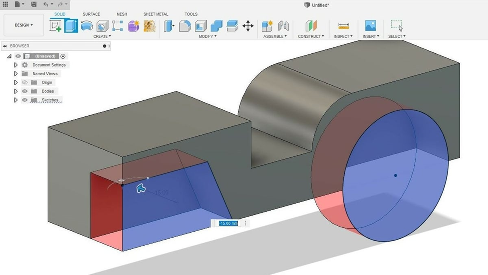
You can select a new surface from the extruded object to sketch on. To do so, select “Create Sketch” and select the surface you would like to sketch on as the plane. Afterwards continue to sketch like normal.
Extrusion can also be used to cut. Sketch on the surface of the shape the geometry you would like to cut. Select “Extrude” tool and select the shapes you would like to cut. To remove material, enter a negative value in the dimension window. This indicates the direction you would like the extrusion to occur. On the screen, it will display a red region to indicate material removal. Press enter to confirm the operation.
Mirror
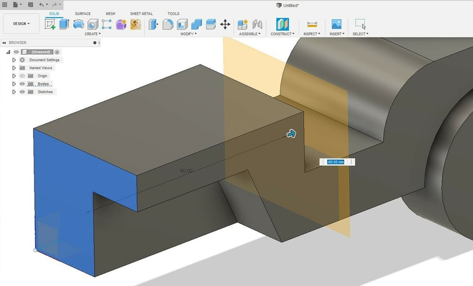
The mirror tool is an extremely powerful tool that can save the user a lot of time in creating the 3D models. This is especially useful when creating symmetrical objects. It allows users to mirror solid or small features. It does require the user to define the plane to mirror the features. There are many ways to create the plane. One of which is to “Offset Plane”
Under the “Construct” drop-down menu from the toolbar, select “Offset Plane”. Select a surface to offset from. This surface should be parallel from the plane you would like to create. Now enter the dimension you would like to offset the plane from the surface. Press enter when completed.
After the plane has been created, you can now mirror the features. Select “Mirror” under the drop- down menu from “Create” from the toolbar. Under “Type” parameter, you can select bodies, faces, features, or components. After the type has been selected, click on “Select” by Object and then the features you would like to mirror, you can also click on the features from the design history timeline. Then click on “Select” by Mirror Plane and the plane you would to mirror from. Now a preview will be displayed, to confirm press enter.
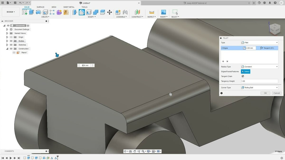
Fillet
Filleting the edges is a feature that is offered in Fusion 360 and not TinkerCAD. It can easily elevate your models. It creates rounded surfaces by adding or removing from a solid model.
- Select “Fillet” under the modify menu from the tool bar.
- Click on the edges you would like to round out.
- Enter a radius value to round the edges out to.
- Click “OK” to finalize.
References
- ↑ CarrusHome (2021). GM Explores 3D printing, generative design for next gen parts. Consulted on 05-05-2022 at https://www.carrushome.com/en/gm-explores-3d-printing-generative-design-for-next-gen-parts/
